Shimane.
1 ABWR unit at Shimane, beside the ABWR plant concept. The 3D model shows how the ABWR design works; it is not Shimane's actual layout.
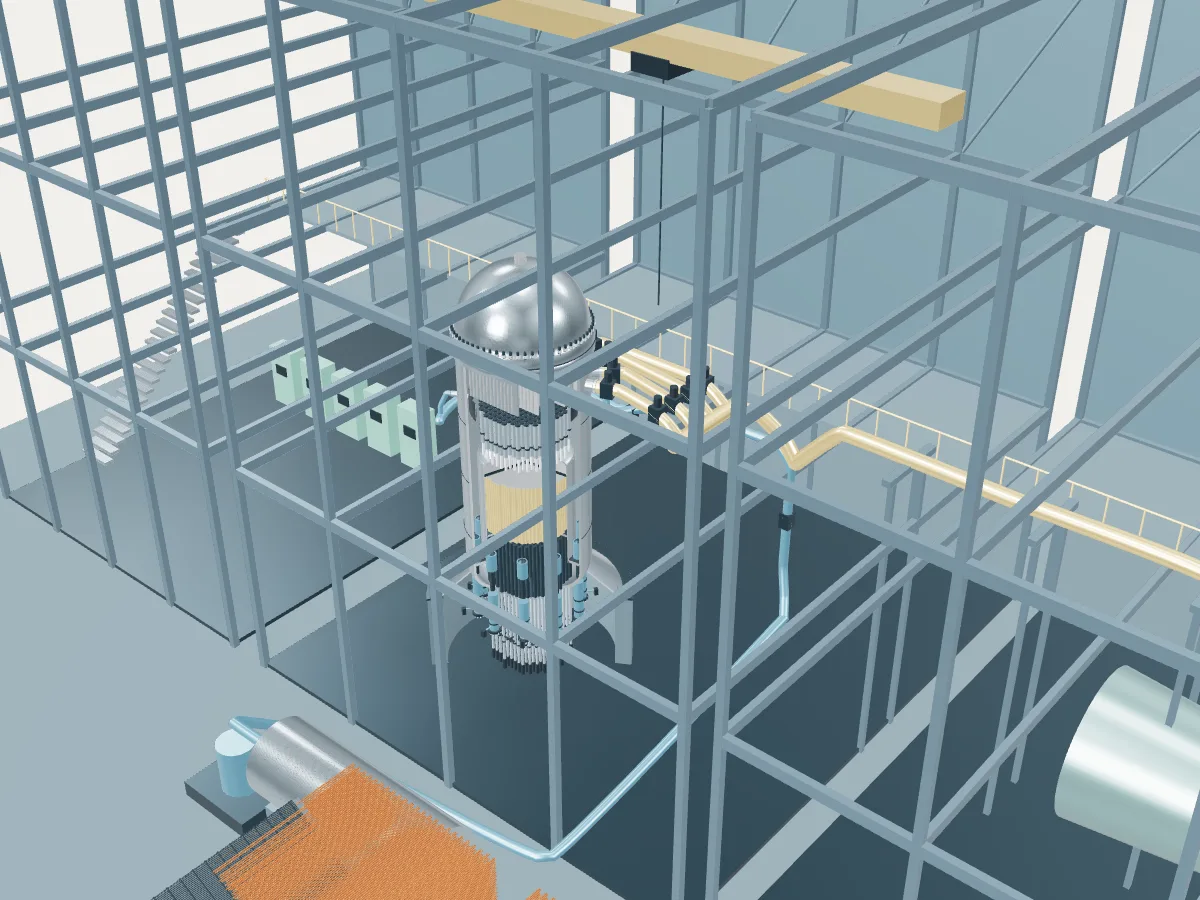 DESIGN CONCEPT · NOT A SIMULATION
The ABWR plant concept.
The ABWR design’s concept, not Shimane. The model shows how an ABWR plant works, drawn from the design’s public description, in the generic layout every design in the plant library shares: the reactor island, a turbine hall, air-cooled condensers and a grid connection. It does not show Shimane's buildings, number of units, cooling or equipment.
The concept follows the generic ABWR described to the IAEA, rated at 3,926 MWt and 1,350 MWe net. Built units differ: Kashiwazaki-Kariwa 6 and 7 are rated 1,315 MWe net, Hamaoka 5 1,325 MWe and Shika 2 1,304 MWe; Hamaoka 5 introduced a sealless fine-motion drive, and the UK version powers all its internal pumps through motor-generator sets. The vessel is drawn at 0.5 scale in the plant library’s shared building frame, and the reinforced concrete containment and its suppression pool are left out.
A large boiling water reactor of about 1,350 MWe. Water boils in an 872-bundle core, and separators and a dryer above it send dry steam straight from the vessel to the turbine, with no steam generator. Ten pumps built into the bottom of the vessel drive the water round in place of the external recirculation loops of earlier boiling water reactors, and 205 fine-motion control rod drives enter from below. A reinforced concrete containment with a suppression pool surrounds the vessel.
- Fuel
- Uranium dioxide
- Reaction
- Splitting heavy nuclei
- Energy transfer
- Direct cycle with internal recirculation pumps
Boiling water reactor
Water boils inside the reactor vessel and the steam goes straight to the turbine. One loop, no steam generators.
The ABWR by its published numbers.
Each figure is the design’s own, as its source publishes it, with the page it is on. They describe the design, not any station: built units may be uprated, and the station’s own capacities are in its unit table. Nothing here is computed.
| Thermal power | 3,926 MWtIAEA ARIS status report, Table 2, Fuel/Core, p. 7; §5.2, p. 14 |
|---|---|
| Gross electric output | approximately 1,420 MWeIAEA ARIS status report, §5.5 Secondary side, p. 17 |
| Net electric output (design) | 1,350 MWeIAEA ARIS status report, Table 2, capacity to electric grid, p. 5 |
| Turbine speed (60 Hz design) | 1,800 rpmIAEA ARIS status report, §5.5 Secondary side, p. 17 |
| Fuel bundles | 872IAEA ARIS status report, Table 2, p. 7; §5.2, p. 14 |
|---|---|
| Bundle lattice | 10 × 10, squareIAEA ARIS status report, Table 1, p. 5 |
| Control rod drives | 205, fine-motion, from belowIAEA ARIS status report, §5.2, p. 14 |
| Refuelling cycle | 12-24 monthsIAEA ARIS status report, Table 2, Fuel/Core, p. 7 |
| Coolant loops (NSSS layout) | Direct cycleIAEA ARIS status report, Table 1, NSSS layout, p. 4 |
|---|---|
| Recirculation pumps | 10, reactor internal pumps, variable speedIAEA ARIS status report, Table 1, p. 4; reactor recirculation system, p. 24 |
| Reactor pressure | 7.07 MPaIAEA ARIS status report, Table 2, Plant Infrastructure, p. 6 |
| Core inlet temperature | 278 °CIAEA ARIS status report, Table 2, p. 6 |
| Core outlet temperature | 288 °CIAEA ARIS status report, Table 2, p. 6 |
| Steam pressure | 7.07 MPaIAEA ARIS status report, Table 2, Nuclear System, p. 9 |
|---|---|
| Steam temperature | 288 °CIAEA ARIS status report, Table 2, Nuclear System, p. 9 |
| Steam flow | 2,122 kg/sIAEA ARIS status report, Table 2, Nuclear System, p. 9 |
| Feedwater temperature | 216 °CIAEA ARIS status report, Table 2, Nuclear System, p. 9; §5.5, p. 17 |
| Reactor vessel diameter (inside or outside not stated) | 7,100 mmIAEA ARIS status report, Table 2, NSSS largest component diameter, p. 6 |
|---|---|
| Reactor vessel length | 21,000 mmIAEA ARIS status report, Table 2, NSSS largest component length, p. 6 |
| Containment | Pressure suppression; reinforced concrete containment vessel with a steel linerIAEA ARIS status report, Table 2, containment type, p. 6; §5.6, p. 19 |
| Design life | 60 yearsIAEA ARIS status report, Table 2, Plant Infrastructure, p. 5 |
Where the ABWR’s heat goes.
One unit at its design rating, from the published figures above. Most of the reactor’s heat leaves through the condenser to the cooling water or air; the rest becomes electricity, some of which runs the plant itself. A figure marked “derived” is plain arithmetic on published ones; nothing is simulated.
- Reactor heat
- 3,926 MWtIAEA ARIS status report, Table 2, Fuel/Core, p. 7; §5.2, p. 14
- Gross electricity
- about 1,420 MWeIAEA ARIS status report, §5.5 Secondary side, p. 17
- Net to the grid
- 1,350 MWeIAEA ARIS status report, Table 2, capacity to electric grid, p. 5
- Used in the plant
- about 70 MWeDerived: about 1,420 MWe gross less 1,350 MWe net
- Heat rejected through the condenser
- about 2,506 MWtDerived: 3,926 MWt of reactor heat less about 1,420 MWe gross
- Net efficiency
- about 34.4 %Derived: 1,350 MWe net of 3,926 MWt
- 01 Heat source
- Reactor heat
- 3,926 MWtIAEA ARIS status report, Table 2, Fuel/Core, p. 7; §5.2, p. 14
- Reactor pressure
- 7.07 MPaIAEA ARIS status report, Table 2, Plant Infrastructure, p. 6
- Core inlet to outlet
- 278 → 288 °CIAEA ARIS status report, Table 2, p. 6
- 02 Steam
- Steam pressure
- 7.07 MPaIAEA ARIS status report, Table 2, Nuclear System, p. 9
- Steam temperature
- 288 °CIAEA ARIS status report, Table 2, Nuclear System, p. 9
- Steam flow
- 2,122 kg/sIAEA ARIS status report, Table 2, Nuclear System, p. 9
- 03 Turbine and generator
- Gross electricity
- about 1,420 MWeIAEA ARIS status report, §5.5 Secondary side, p. 17
- Turbine speed (60 Hz design)
- 1,800 rpmIAEA ARIS status report, §5.5 Secondary side, p. 17
- 04 Cooling and return
- Heat rejected
- about 2,506 MWtDerived
- Feedwater temperature
- 216 °CIAEA ARIS status report, Table 2, Nuclear System, p. 9; §5.5, p. 17
- 05 Grid connection
- Net to the grid
- 1,350 MWeIAEA ARIS status report, Table 2, capacity to electric grid, p. 5
- Used in the plant
- about 70 MWeDerived
- Net efficiency
- about 34.4 %Derived
Shimane’s ABWR unit at design rating
It would take 3,926 MWt of heat from its reactor and reject about 2,510 MWt to its cooling. Its own published net capacity is 1,325 MWe.
Shimane as one power plant.
Every unit on the site, from the atlas’s unit records: each reactor drives its own generator, which feeds the station’s switchyard and the grid. This is a schematic of how the units connect, not the station’s layout; the atlas records no buildings, cooling, switchyard arrangement or grid voltage.
- Operating · 1
- Under construction · 1
- Shut down · 1
- On this page
- Operating
- 1 unit · 789 MWe netPublished net capacities, from the unit table
- Being built or planned
- 1 unit · 1,325 MWe net
- Shut down
- 1 unit · 439 MWe net
- Plant concepts here
- BWR reference (2) · ABWR (1)