Shimane.
2 BWR units at Shimane, beside the boiling water reference plant concept. The 3D model shows how the family works; it is not Shimane's actual layout.
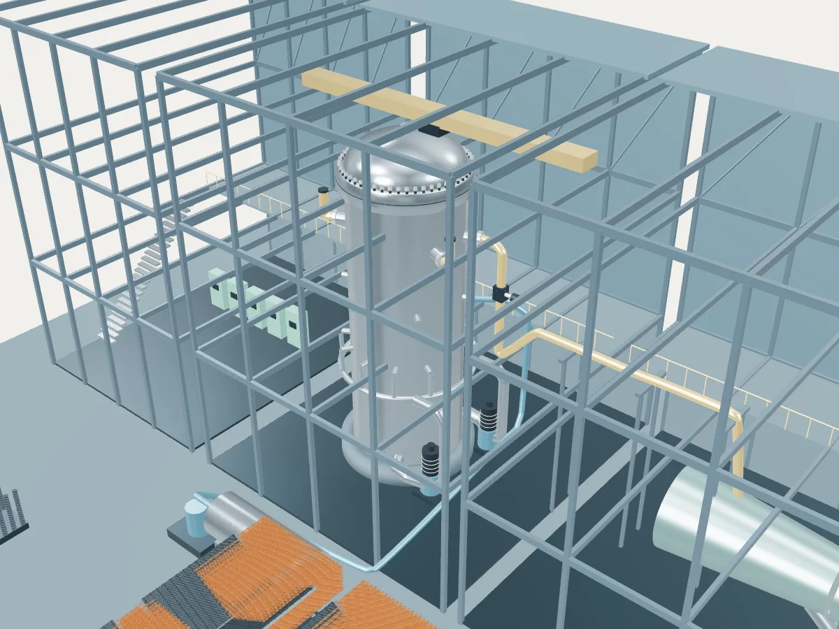 REFERENCE CONCEPT · NOT A SIMULATION
The boiling water reference plant.
The family’s reference concept, not Shimane. The model illustrates a boiling water reactor concept, with the generic layout every design in the plant library shares: the reactor island, a turbine hall, air-cooled condensers and a grid connection. It does not show Shimane's buildings, number of units, cooling or equipment.
The concept has external recirculation loops, as on earlier boiling water reactor generations. Advanced boiling water reactors (ABWR) move the recirculation pumps inside the vessel, and their units open the ABWR concept.
Fission boils water directly inside the reactor vessel. Separators and a dryer above the core remove droplets before steam leaves for the turbine, so this cycle has no steam generator.
- Fuel
- Uranium dioxide
- Reaction
- Splitting heavy nuclei
- Energy transfer
- Direct cycle: water boils in the vessel
Boiling water reactor
Water boils inside the reactor vessel and the steam goes straight to the turbine. One loop, no steam generators.
Shimane as one power plant.
Every unit on the site, from the atlas’s unit records: each reactor drives its own generator, which feeds the station’s switchyard and the grid. This is a schematic of how the units connect, not the station’s layout; the atlas records no buildings, cooling, switchyard arrangement or grid voltage.
- Operating · 1
- Under construction · 1
- Shut down · 1
- On this page
- Operating
- 1 unit · 789 MWe netPublished net capacities, from the unit table
- Being built or planned
- 1 unit · 1,325 MWe net
- Shut down
- 1 unit · 439 MWe net
- Plant concepts here
- BWR reference (2) · ABWR (1)