Darlington.
1 BWRX-300 unit at Darlington, beside the BWRX-300 plant concept. The 3D model shows how the BWRX-300 design works; it is not Darlington's actual layout.
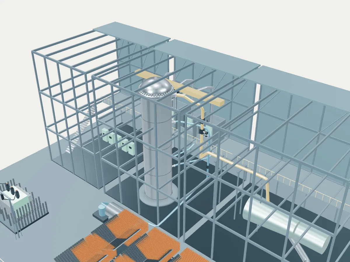 DESIGN CONCEPT · NOT A SIMULATION
The BWRX-300 plant concept.
The BWRX-300 design’s concept, not Darlington. The model shows how a BWRX-300 plant works, drawn from the design’s public description, in the generic layout every design in the plant library shares: the reactor island, a turbine hall, air-cooled condensers and a grid connection. It does not show Darlington's buildings, number of units, cooling or equipment.
The published design sets the reactor building below grade. The concept instead stands the vessel in the plant library's shared building frame, with its lower head under the slab and the isolation condenser pools on a mezzanine behind it.
A boiling water reactor of about 300 MWe. Water boils in the core and rises through a tall chimney, which keeps it circulating without recirculation pumps; separators and a dryer above send the steam straight to the turbine. Three isolation condenser trains give steam a second path: it condenses in tubes inside water pools and drains back to the vessel.
- Fuel
- Uranium dioxide
- Reaction
- Splitting heavy nuclei
- Energy transfer
- Direct cycle with natural circulation
Boiling water reactor
Water boils inside the reactor vessel and the steam goes straight to the turbine. One loop, no steam generators.
The BWRX-300 by its published numbers.
Each figure is the design’s own, as its source publishes it, with the page it is on. They describe the design, not any station: built units may be uprated, and the station’s own capacities are in its unit table. Nothing here is computed.
| Thermal power | 870 MWtGE Vernova Hitachi, BWRX-300 General Description, Rev. J, Table 2-1, p. 28 |
|---|---|
| Gross electric output | ~316 MWeGE Vernova Hitachi, BWRX-300 General Description, Rev. J, Table 2-1, p. 28 |
| Fuel bundles | 240GE Vernova Hitachi, BWRX-300 General Description, Rev. J, Table 2-1, p. 29 |
|---|---|
| Active core height | 3.8 mGE Vernova Hitachi, BWRX-300 General Description, Rev. J, §3.1.1, p. 31 |
| Control rods | 57, cruciform, fine-motion drivesGE Vernova Hitachi, BWRX-300 General Description, Rev. J, Table 2-1, p. 29 |
| Cycle length | 12–24 monthsGE Vernova Hitachi, BWRX-300 General Description, Rev. J, §4.3, p. 51 |
| Coolant circulation | Direct cycle, natural circulationGE Vernova Hitachi, BWRX-300 General Description, Rev. J, Table 2-1, p. 28 |
|---|---|
| Reactor operating pressure | 7.2 (absolute) MPaGE Vernova Hitachi, BWRX-300 General Description, Rev. J, Table 2-1, p. 28 |
| Vessel inside diameter | ≈4.2 (Table 2-1 rounds to 4) mGE Vernova Hitachi, BWRX-300 General Description, Rev. J, §3.1.1, p. 31; Table 2-1, p. 29 |
|---|---|
| Vessel inside height | ≈27.36 mGE Vernova Hitachi, BWRX-300 General Description, Rev. J, §3.1.1, p. 31 |
| Vessel wall, with cladding | ≈135.4 mmGE Vernova Hitachi, BWRX-300 General Description, Rev. J, §3.1.1, p. 31 |
| Primary containment | Steel-plate composite containment vesselGE Vernova Hitachi, BWRX-300 General Description, Rev. J, Table 2-1, p. 29 |
| Design life | 60 (extendable to 80) yearsGE Vernova Hitachi, BWRX-300 General Description, Rev. J, §17.1, p. 100 |
Where the BWRX-300’s heat goes.
One unit at its design rating, from the published figures above. Most of the reactor’s heat leaves through the condenser to the cooling water or air; the rest becomes electricity, some of which runs the plant itself. A figure marked “derived” is plain arithmetic on published ones; nothing is simulated.
- Reactor heat
- 870 MWtGE Vernova Hitachi, BWRX-300 General Description, Rev. J, Table 2-1, p. 28
- Gross electricity
- about 316 MWeGE Vernova Hitachi, BWRX-300 General Description, Rev. J, Table 2-1, p. 28
- Heat rejected through the condenser
- about 554 MWtDerived: 870 MWt of reactor heat less about 316 MWe gross
- 01 Heat source
- Reactor heat
- 870 MWtGE Vernova Hitachi, BWRX-300 General Description, Rev. J, Table 2-1, p. 28
- Reactor operating pressure
- 7.2 (absolute) MPaGE Vernova Hitachi, BWRX-300 General Description, Rev. J, Table 2-1, p. 28
- 02 Steam
- 03 Turbine and generator
- Gross electricity
- about 316 MWeGE Vernova Hitachi, BWRX-300 General Description, Rev. J, Table 2-1, p. 28
- 04 Cooling and return
- Heat rejected
- about 554 MWtDerived
- 05 Grid connection
Darlington’s BWRX-300 unit at design rating
It would take 870 MWt of heat from its reactor and reject about 550 MWt to its cooling. Its own published net capacity is 300 MWe.
Darlington as one power plant.
Every unit on the site, from the atlas’s unit records: each reactor drives its own generator, which feeds the station’s switchyard and the grid. This is a schematic of how the units connect, not the station’s layout; the atlas records no buildings, cooling, switchyard arrangement or grid voltage.
- Operating · 4
- Under construction · 1
- Planned · 1
- On this page
- Operating
- 4 units · 3,524 MWe netPublished net capacities, from the unit table
- Being built or planned
- 2 units · 300 MWe net
- Plant concepts here
- PHWR reference (5) · BWRX-300 (1)