Gas Dynamic Trap.
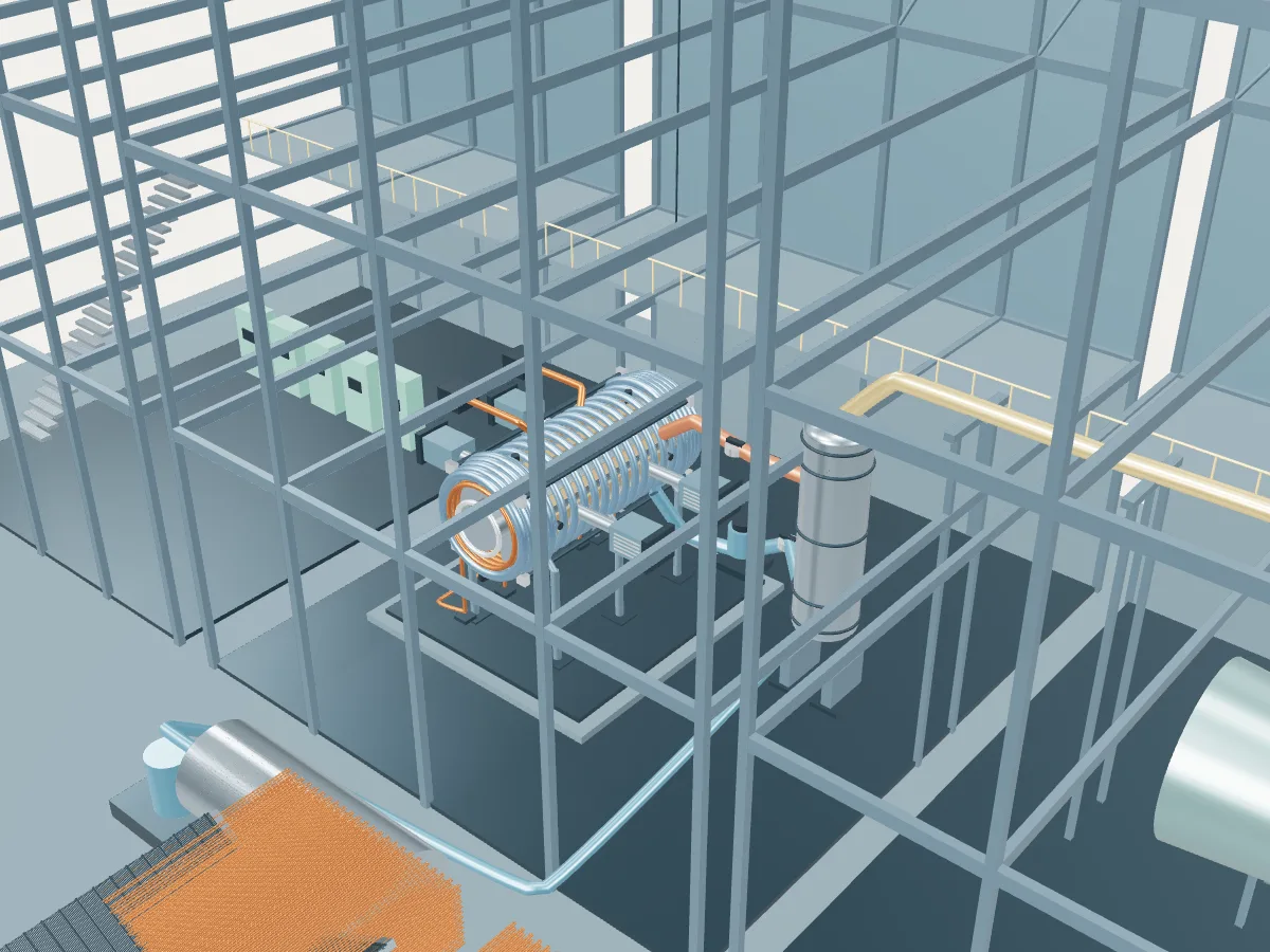
Gas Dynamic Trap at Novosibirsk (Akademgorodok), beside the magnetic mirror reference plant concept. The 3D model shows how the family works; it is not Gas Dynamic Trap's actual layout.
 REFERENCE CONCEPT · NOT A SIMULATION
The magnetic mirror reference plant.
The family’s reference concept, not Gas Dynamic Trap. The model illustrates a magnetic mirror concept, with the generic layout every design in the plant library shares: the reactor island, a turbine hall, air-cooled condensers and a grid connection. It does not show Gas Dynamic Trap's buildings, number of units, cooling or equipment.
A linear magnetic system strengthens the field at both ends to confine plasma between mirror regions. A surrounding blanket and heat exchanger connect the concept to the shared cycle.
- Fuel
- Hydrogen-isotope plasma
- Reaction
- Combining light nuclei
- Energy transfer
- Blanket heat-transfer loop
Magnetic mirror
A straight plasma column plugged at both ends by stronger fields that reflect particles back toward the middle.