Shin-Hanul.
4 APR1400 units at Shin-Hanul, beside the APR1400 plant concept. The 3D model shows how the APR1400 design works; it is not Shin-Hanul's actual layout.
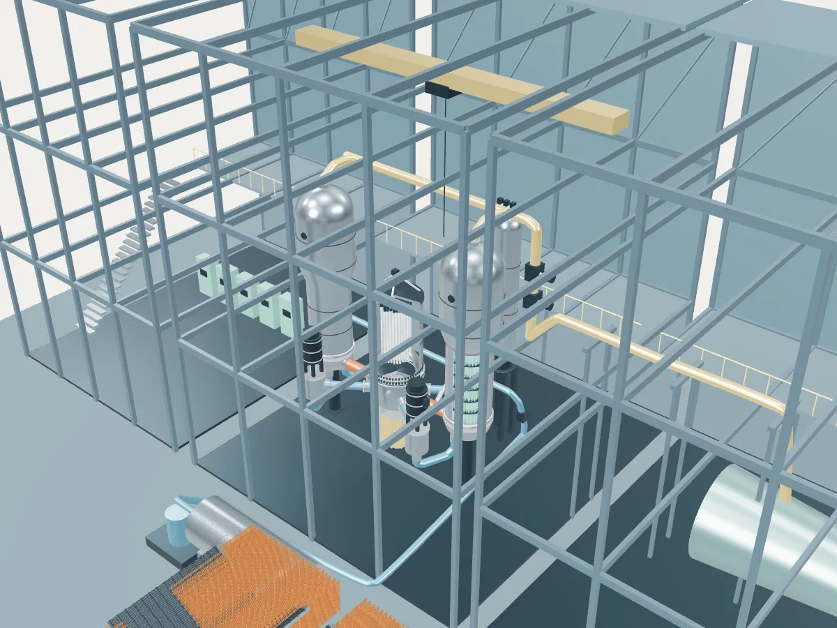 DESIGN CONCEPT · NOT A SIMULATION
The APR1400 plant concept.
The APR1400 design’s concept, not Shin-Hanul. The model shows how an APR1400 plant works, drawn from the design’s public description, in the generic layout every design in the plant library shares: the reactor island, a turbine hall, air-cooled condensers and a grid connection. It does not show Shin-Hanul's buildings, number of units, cooling or equipment.
The concept follows the APR1400 standard design. Built units differ in places: Shin-Kori 3 and 4 in Korea are the reference plant, while later Korean units, the four Barakah units in the UAE and the US-certified version thicken the containment wall against aircraft impact and change some severe-accident features. The coolant system is drawn at 0.45 of full size, and the concrete containment and its refueling water storage tank are not drawn.
A two-loop pressurized water reactor of 1,400 MWe. Water at 15.5 MPa carries heat from a 241-assembly core through two hot legs to two large U-tube steam generators with integral economizers, and four vertical pumps, one in each of four cold legs, return it to the vessel. Safety injection pumps feed borated water straight into the vessel from a refueling water storage tank inside the containment, which also catches steam from the pressurizer relief valves.
- Fuel
- Uranium dioxide
- Reaction
- Splitting heavy nuclei
- Energy transfer
- Two-loop pressurized water primary circuit
Pressurized water reactor
Water held at around 155 bar stays liquid as it carries heat from the core to steam generators, where a second loop boils. The most common reactor on Earth.
The APR1400 by its published numbers.
Each figure is the design’s own, as its source publishes it, with the page it is on. They describe the design, not any station: built units may be uprated, and the station’s own capacities are in its unit table. Nothing here is computed.
| Thermal power | 3,983 MWtIAEA ARIS status report, Table 2, Single Core Thermal Power, p. 6 |
|---|---|
| Gross electric output | 1,465 MWeIAEA ARIS status report, §1 Overview, p. 1 |
| Net electric output | 1,400 MWeIAEA ARIS status report, §1 Overview, p. 1; Table 2, Capacity to Electric Grid, p. 5 |
| Turbine speed | 1,800 rpmIAEA-TECDOC-1391 (2004), §4.9.8 Technical data, Turbine plant, printed p. 275 |
| Fuel assemblies | 241IAEA ARIS status report, Table 2, Number of Fuel Units, p. 6; §5.2, p. 18 |
|---|---|
| Assembly rod array | 16 × 16, squareIAEA ARIS status report, §5.2 Reactor Core and Fuel, p. 18; Table 1, Fuel Lattice Shape, p. 4 |
| Fuel rods per assembly | 236IAEA ARIS status report, §5.2 Reactor Core and Fuel, p. 18; Table 1, p. 4 |
| Active core height | 3.81 mIAEA ARIS status report, Table 2, Active Core Height, p. 9 |
| Equivalent core diameter | 3.63 mIAEA ARIS status report, Table 2, Equivalent Core Diameter, p. 9 |
| Control element assemblies | 93 (81 full strength, the rest part strength)IAEA ARIS status report, §5.2 Reactor Core and Fuel, p. 18 |
| Enrichment | 4.65 %IAEA ARIS status report, Table 2, Enrichment, p. 6 |
| Refueling cycle | 18 monthsIAEA ARIS status report, Table 2, Refuelling Cycle, p. 6 |
| Coolant loops | 2 (each one hot leg, two cold legs)IAEA ARIS status report, §5.1 Primary Circuit, p. 11 |
|---|---|
| Steam generators | 2, vertical U-tube with integral economizerIAEA ARIS status report, Table 2, Steam Generator Design, p. 6; §5.1, p. 14 |
| Reactor coolant pumps | 4, vertical single-stage centrifugal, one in each cold legIAEA ARIS status report, Table 1, Primary Circulation, p. 3; §5.1, p. 16 |
| Primary pressure | 15.5 MPaIAEA ARIS status report, Table 2, NSSS Operating Pressure (primary side), p. 5 |
| Primary coolant flow | 21,000 kg/sIAEA ARIS status report, Table 2, Nominal Coolant Flow Rate (primary), p. 5 |
| Core inlet temperature | 290.6 °CIAEA ARIS status report, Table 2, Core Inlet Coolant Temperature, p. 5 |
| Core outlet temperature | 323.9 °CIAEA ARIS status report, Table 2, Core Outlet Coolant Temperature, p. 5 |
| Steam pressure | 6.9 MPaIAEA ARIS status report, Table 2, System Steam Pressure, p. 8 |
|---|---|
| Steam temperature | 285 °CIAEA ARIS status report, Table 2, System Steam Temperature, p. 8 |
| Steam flow per steam generator | 4.070 × 10⁶ kg/hOECD-NEA MDEP, TR-APR1400-01, Table 1.2, printed p. 6 |
| Feedwater temperature at full power | 232.22 °COECD-NEA MDEP, TR-APR1400-01, Table 1.2, printed p. 6 |
| Vessel inside diameter | 4,630 mmIAEA-TECDOC-1391 (2004), §4.9.8 Technical data, Reactor pressure vessel, printed p. 273 |
|---|---|
| Vessel total height | 15,280 mmIAEA-TECDOC-1391 (2004), §4.9.8 Technical data, Reactor pressure vessel, printed p. 273 |
| Vessel shell wall | 230 mmIAEA-TECDOC-1391 (2004), §4.9.8 Technical data, Reactor pressure vessel, printed p. 273 |
| Containment | Steel-lined post-tensioned prestressed concrete cylinder, 45.7 m diameter, 76.4 m highIAEA-TECDOC-1391 (2004), §4.9.8 Technical data, Containment, printed p. 274 |
| Design life | 60 yearsIAEA ARIS status report, Table 2, Design Life, p. 4 |
Where the APR1400’s heat goes.
One unit at its design rating, from the published figures above. Most of the reactor’s heat leaves through the condenser to the cooling water or air; the rest becomes electricity, some of which runs the plant itself. A figure marked “derived” is plain arithmetic on published ones; nothing is simulated.
- Reactor heat
- 3,983 MWtIAEA ARIS status report, Table 2, Single Core Thermal Power, p. 6
- Gross electricity
- 1,465 MWeIAEA ARIS status report, §1 Overview, p. 1
- Net to the grid
- 1,400 MWeIAEA ARIS status report, §1 Overview, p. 1; Table 2, Capacity to Electric Grid, p. 5
- Used in the plant
- 65 MWeDerived: 1,465 MWe gross less 1,400 MWe net
- Heat rejected through the condenser
- 2,518 MWtDerived: 3,983 MWt of reactor heat less 1,465 MWe gross
- Net efficiency
- about 35.1 %Derived: 1,400 MWe net of 3,983 MWt
- 01 Heat source
- Reactor heat
- 3,983 MWtIAEA ARIS status report, Table 2, Single Core Thermal Power, p. 6
- Primary pressure
- 15.5 MPaIAEA ARIS status report, Table 2, NSSS Operating Pressure (primary side), p. 5
- Core inlet to outlet
- 290.6 → 323.9 °CIAEA ARIS status report, Table 2, Core Outlet Coolant Temperature, p. 5
- Primary coolant flow
- 21,000 kg/sIAEA ARIS status report, Table 2, Nominal Coolant Flow Rate (primary), p. 5
- 02 Steam
- Steam generators
- 2, vertical U-tube with integral economizerIAEA ARIS status report, Table 2, Steam Generator Design, p. 6; §5.1, p. 14
- Steam pressure
- 6.9 MPaIAEA ARIS status report, Table 2, System Steam Pressure, p. 8
- Steam temperature
- 285 °CIAEA ARIS status report, Table 2, System Steam Temperature, p. 8
- Steam flow per steam generator
- 4.070 × 10⁶ kg/hOECD-NEA MDEP, TR-APR1400-01, Table 1.2, printed p. 6
- 03 Turbine and generator
- Gross electricity
- 1,465 MWeIAEA ARIS status report, §1 Overview, p. 1
- Turbine speed
- 1,800 rpmIAEA-TECDOC-1391 (2004), §4.9.8 Technical data, Turbine plant, printed p. 275
- 04 Cooling and return
- Heat rejected
- 2,518 MWtDerived
- Feedwater temperature at full power
- 232.22 °COECD-NEA MDEP, TR-APR1400-01, Table 1.2, printed p. 6
- 05 Grid connection
- Net to the grid
- 1,400 MWeIAEA ARIS status report, §1 Overview, p. 1; Table 2, Capacity to Electric Grid, p. 5
- Used in the plant
- 65 MWeDerived
- Net efficiency
- about 35.1 %Derived
Shin-Hanul’s 2 operating APR1400 units at design rating
Together they would take 7,966 MWt of heat from their reactors and reject 5,036 MWt to their cooling. Their own published net capacities add to 2,680 MWe.
Shin-Hanul as one power plant.
Every unit on the site, from the atlas’s unit records: each reactor drives its own generator, which feeds the station’s switchyard and the grid. This is a schematic of how the units connect, not the station’s layout; the atlas records no buildings, cooling, switchyard arrangement or grid voltage.
- Operating · 2
- Under construction · 2
- On this page
- Operating
- 2 units · 2,680 MWe netPublished net capacities, from the unit table
- Being built or planned
- 2 units · 2,680 MWe net
- Heat at design rating
- 7,966 MWt in, 5,040 MWt rejectedDerived: 2 operating units of a named design, each at its design’s published rating
- Plant concepts here
- APR1400 (4)