Summer.
1 PWR unit at Summer, beside the pressurized water reference plant concept. The 3D model shows how the family works; it is not Summer's actual layout.
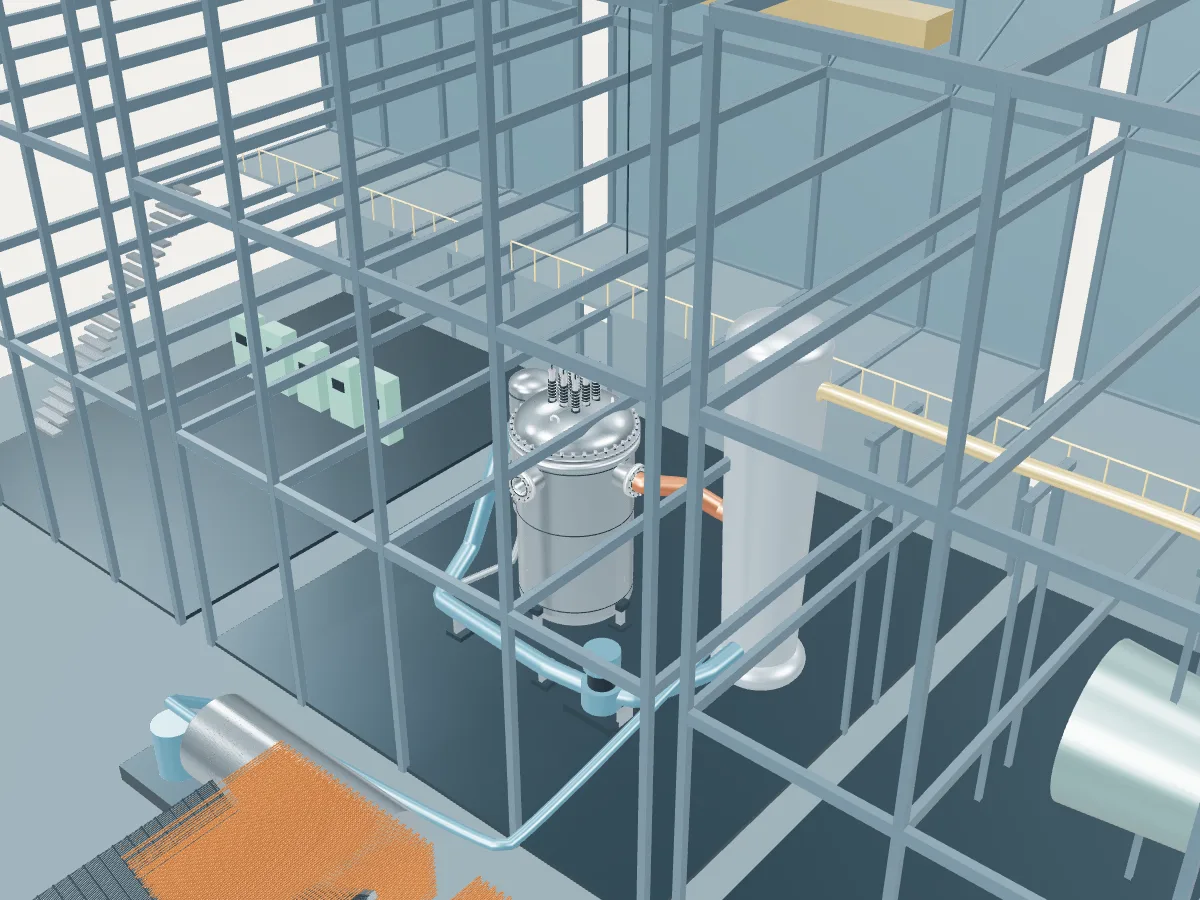 REFERENCE CONCEPT · NOT A SIMULATION
The pressurized water reference plant.
The family’s reference concept, not Summer. The model illustrates a pressurized water reactor concept, with the generic layout every design in the plant library shares: the reactor island, a turbine hall, air-cooled condensers and a grid connection. It does not show Summer's buildings, number of units, cooling or equipment.
Commercial pressurized water reactors run several coolant loops, typically two to four, and the VVER-440 six, each with its own steam generator and pump; the concept shows one. Units of the VVER, AP1000, EPR, HPR1000 and APR1400 designs open their own concepts, drawn with their real loop counts.
Fission heats water inside the pressure vessel. The primary water stays liquid under pressure and transfers its heat to a separate steam circuit.
- Fuel
- Uranium dioxide
- Reaction
- Splitting heavy nuclei
- Energy transfer
- Pressurized-water primary loop
Pressurized water reactor
Water held at around 155 bar stays liquid as it carries heat from the core to steam generators, where a second loop boils. The most common reactor on Earth.
Summer as one power plant.
Every unit on the site, from the atlas’s unit records: each reactor drives its own generator, which feeds the station’s switchyard and the grid. This is a schematic of how the units connect, not the station’s layout; the atlas records no buildings, cooling, switchyard arrangement or grid voltage.
- Operating · 1
- Suspended · 2
- On this page
- Operating
- 1 unit · 900 MWe netPublished net capacities, from the unit table
- Suspended
- 2 units · 2,234 MWe net
- Plant concepts here
- AP1000 (2) · PWR reference (1)