Rostov.
4 VVER-1000 units at Rostov, beside the VVER-1000 plant concept. The 3D model shows how the VVER-1000 design works; it is not Rostov's actual layout.
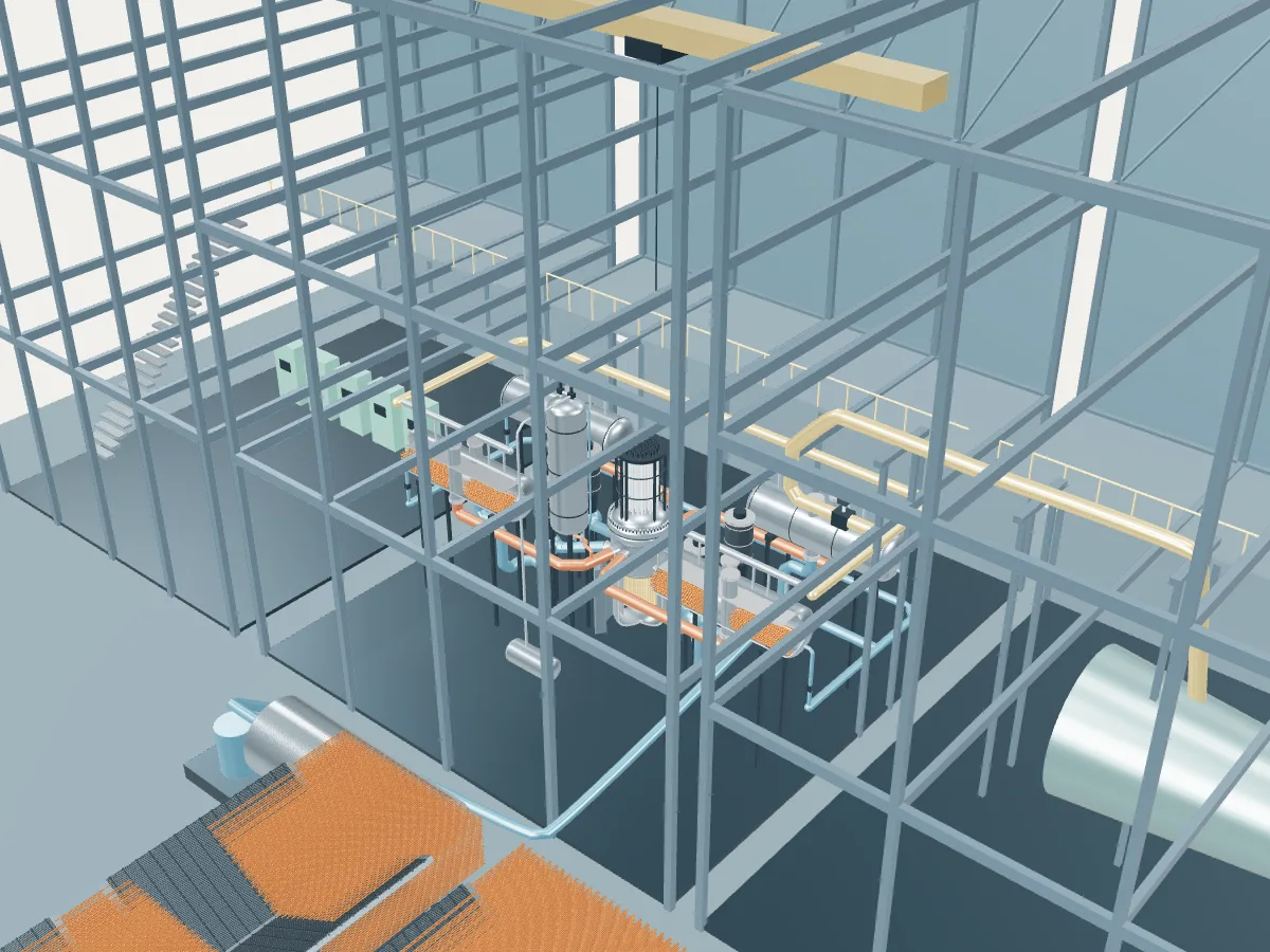 DESIGN CONCEPT · NOT A SIMULATION
The VVER-1000 plant concept.
The VVER-1000 design’s concept, not Rostov. The model shows how a VVER-1000 plant works, drawn from the design’s public description, in the generic layout every design in the plant library shares: the reactor island, a turbine hall, air-cooled condensers and a grid connection. It does not show Rostov's buildings, number of units, cooling or equipment.
The concept is the V-320, the most built VVER-1000; units of the other VVER-1000 models that open it differ in detail the concept does not show. The prestressed containment is not drawn, and the four loops are compressed to fit the plant library’s shared building frame.
A Soviet-designed pressurized water reactor of 3000 MWt, more than twice the VVER-440’s output from fewer, larger loops. Water at 15.7 MPa leaves the core at 320 °C through four loops of 850 mm pipe, each with a horizontal steam generator 14.5 m long and a main coolant pump; unlike the VVER-440, the loops have no main gate valves. The core holds 163 hexagonal assemblies and 61 control clusters, and a prestressed concrete containment encloses the whole reactor coolant system.
- Fuel
- Uranium dioxide in hexagonal assemblies
- Reaction
- Splitting heavy nuclei
- Energy transfer
- Four loops to horizontal steam generators
Pressurized water reactor
Water held at around 155 bar stays liquid as it carries heat from the core to steam generators, where a second loop boils. The most common reactor on Earth.
The VVER-1000 by its published numbers.
Each figure is the design’s own, as its source publishes it, with the page it is on. They describe the design, not any station: built units may be uprated, and the station’s own capacities are in its unit table. Nothing here is computed.
| Thermal power | 3,000 MWtGRS-92 assessment (1992), Table 2-1, p. 35 (WWER-1000 column; identified as W-320 on p. 5) |
|---|---|
| Net efficiency | 30 %GRS-92 assessment (1992), Table 2-1, p. 35 |
| Turbine speed (one turbine) | 3,000 rpmGRS-92 assessment (1992), Table 2-1, p. 36 |
| Fuel assemblies | 163GRS-92 assessment (1992), Table 2-1, p. 35 |
|---|---|
| Assembly type | Hexagonal, without shroudGRS-92 assessment (1992), Table 2-1, p. 35 |
| Fuel rods per assembly | 312GRS-92 assessment (1992), Table 2-1, p. 35 |
| Fuel rod active length | 3,550 mmGRS-92 assessment (1992), Table 2-1, p. 35 |
| Control assemblies | 61, 18 rods each (boron carbide)GRS-92 assessment (1992), Table 2-1, p. 35 |
| Coolant loops | 4GRS-92 assessment (1992), Table 2-1, p. 36 |
|---|---|
| Steam generators | 4, horizontalGRS-92 assessment (1992), Table 2-1, p. 36 (four loops; horizontal type) |
| Main coolant pumps | 4, 1000 rpmSÚJB national report (2016), Annex 1, p. 11/18 (Temelín, main coolant pump) |
| Primary system pressure | 15.7 MPaGRS-92 assessment (1992), Table 2-1, p. 35 |
| Reactor coolant flow | 84,800 m³/hSÚJB national report (2016), Annex 1, p. 11/18 (Temelín, reactor cooling system) |
| Reactor inlet temperature | 290 °CGRS-92 assessment (1992), Table 2-1, p. 35 |
| Reactor outlet temperature | 320 °CGRS-92 assessment (1992), Table 2-1, p. 35 |
| Secondary system pressure | 6.3 MPaGRS-92 assessment (1992), Table 2-1, p. 35 |
|---|---|
| Steam temperature at the generator outlet | 278.5 °CSÚJB national report (2016), Annex 1, p. 11/18 (Temelín, steam generator) |
| Steam per generator | 1,470 t/hSÚJB national report (2016), Annex 1, p. 11/18 (Temelín, steam generator) |
| Vessel inside diameter | 4.5 mSÚJB national report (2016), Annex 1, p. 11/18 (Temelín, reactor technical parameters) |
|---|---|
| Vessel height without the lid | 10.88 mGRS-92 assessment (1992), Table 2-1, p. 36 |
| Vessel cylinder wall | 193 (cladding 7–18 mm) mmSÚJB national report (2016), Annex 1, p. 11/18 (Temelín, reactor technical parameters) |
| Containment | Single-barrier large dry prestressed concrete containment with a metal linerIAEA-TECDOC-1025, §2.1, p. 14 |
Where the VVER-1000’s heat goes.
One unit at its design rating, from the published figures above. Most of the reactor’s heat leaves through the condenser to the cooling water or air; the rest becomes electricity, some of which runs the plant itself. A figure marked “derived” is plain arithmetic on published ones; nothing is simulated.
- Reactor heat
- 3,000 MWtGRS-92 assessment (1992), Table 2-1, p. 35 (WWER-1000 column; identified as W-320 on p. 5)
- Net electricity to the grid
- about 900 MWeDerived: the published net efficiency, 30 %, of 3,000 MWt
- Heat rejected, and the plant’s own use
- about 2,100 MWtDerived: 3,000 MWt of reactor heat less about 900 MWe net
- Net efficiency
- 30 %GRS-92 assessment (1992), Table 2-1, p. 35
- 01 Heat source
- Reactor heat
- 3,000 MWtGRS-92 assessment (1992), Table 2-1, p. 35 (WWER-1000 column; identified as W-320 on p. 5)
- Primary system pressure
- 15.7 MPaGRS-92 assessment (1992), Table 2-1, p. 35
- Core inlet to outlet
- 290 → 320 °CGRS-92 assessment (1992), Table 2-1, p. 35
- Reactor coolant flow
- 84,800 m³/hSÚJB national report (2016), Annex 1, p. 11/18 (Temelín, reactor cooling system)
- 02 Steam
- Steam generators
- 4, horizontalGRS-92 assessment (1992), Table 2-1, p. 36 (four loops; horizontal type)
- Secondary system pressure
- 6.3 MPaGRS-92 assessment (1992), Table 2-1, p. 35
- Steam temperature at the generator outlet
- 278.5 °CSÚJB national report (2016), Annex 1, p. 11/18 (Temelín, steam generator)
- Steam per generator
- 1,470 t/hSÚJB national report (2016), Annex 1, p. 11/18 (Temelín, steam generator)
- 03 Turbine and generator
- Turbine speed (one turbine)
- 3,000 rpmGRS-92 assessment (1992), Table 2-1, p. 36
- 04 Cooling and return
- Heat rejected and own use
- about 2,100 MWtDerived
- 05 Grid connection
- Net to the grid
- about 900 MWeDerived
- Net efficiency
- 30 %GRS-92 assessment (1992), Table 2-1, p. 35
Rostov’s 4 operating VVER-1000 units at design rating
Together they would take 12,000 MWt of heat from their reactors and reject about 8,400 MWt (with the plant’s own use) to their cooling. Their own published net capacities add to 3,800 MWe.
Rostov as one power plant.
Every unit on the site, from the atlas’s unit records: each reactor drives its own generator, which feeds the station’s switchyard and the grid. This is a schematic of how the units connect, not the station’s layout; the atlas records no buildings, cooling, switchyard arrangement or grid voltage.
- Operating · 4
- On this page
- Operating
- 4 units · 3,800 MWe netPublished net capacities, from the unit table
- Heat at design rating
- about 12,000 MWt in, about 8,400 MWt rejectedDerived: 4 operating units of a named design, each at its design’s published rating
- Plant concepts here
- VVER-1000 (4)