Rooppur.
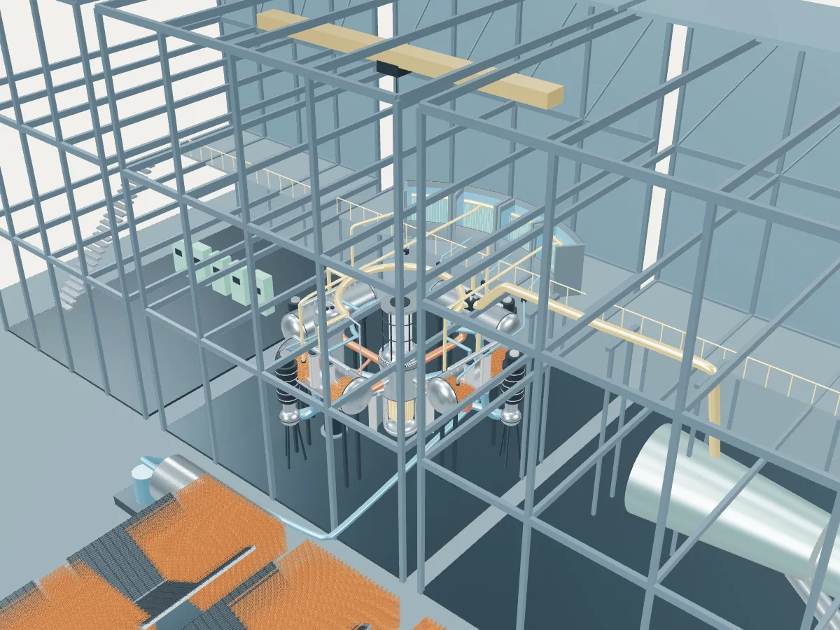
2 VVER-1200 units at Rooppur, beside the VVER-1200 plant concept. The 3D model shows how the VVER-1200 design works; it is not Rooppur's actual layout.
 DESIGN CONCEPT · NOT A SIMULATION
The VVER-1200 plant concept.
The VVER-1200 design’s concept, not Rooppur. The model shows how a VVER-1200 plant works, drawn from the design’s public description, in the generic layout every design in the plant library shares: the reactor island, a turbine hall, air-cooled condensers and a grid connection. It does not show Rooppur's buildings, number of units, cooling or equipment.
The concept is the V-491 version, built at Leningrad II and the Baltic site, whose four passive heat removal trains cool the steam generators through exchangers in water tanks between the two containment shells. The V-392M version of Novovoronezh II and its derivatives V-509 and V-523 share the four horizontal steam generators and the 163-assembly core but cool those exchangers with air instead and rely on more passive systems. The concept is drawn at reduced scale without the double containment or the core catcher, and its tanks stand as an arc on a mezzanine of the plant library’s shared building frame.
A Russian-designed pressurized water reactor of 3200 MWt and about 1170 MWe, developed from the VVER-1000. Water at 16.2 MPa leaves a core of 163 hexagonal fuel assemblies at 329 °C and runs out through four loops, each with a horizontal steam generator, a long drum whose tube bundle lies flat under the boiling water, and a vertical pump that returns it to the reactor. If all power is lost, four passive trains condense steam from the generators in exchangers set in water tanks high in the reactor building and let the water drain back by gravity.
- Fuel
- Uranium dioxide in hexagonal assemblies
- Reaction
- Splitting heavy nuclei
- Energy transfer
- Four loops to horizontal steam generators
Pressurized water reactor
Water held at around 155 bar stays liquid as it carries heat from the core to steam generators, where a second loop boils. The most common reactor on Earth.
The VVER-1200 by its published numbers.
Each figure is the design’s own, as its source publishes it, with the page it is on. They describe the design, not any station: built units may be uprated, and the station’s own capacities are in its unit table. Nothing here is computed.
| Thermal power | 3,200 MWtIAEA ARIS status report, Table 2 (Fuel/Core), p. 7; Table 3, p. 14 |
|---|---|
| Gross electric power | 1,170 MWeIAEA ARIS status report, §1 Overview, p. 1; Table 5, p. 21 |
| Net electric power | 1,082 MWeIAEA ARIS status report, §1 Overview, p. 1 |
| Turbine-generator speed | 3,000 rpmIAEA ARIS status report, §5.7, p. 23 |
| Fuel assemblies | 163IAEA ARIS status report, §5.2, p. 20; Table 2, p. 7 |
|---|---|
| Assembly lattice | HexagonalIAEA ARIS status report, Table 1, p. 5 |
| Fuel rods per assembly | 312IAEA ARIS status report, §5.2, p. 20 |
| Active core height | 3.75 mIAEA ARIS status report, Table 2, p. 9; §5.2, p. 20 |
| Equivalent core diameter | 3.16 mIAEA ARIS status report, Table 2, p. 10 |
| Control assemblies | Up to 121IAEA ARIS status report, §5.2, p. 20 |
| Fuel enrichment | 4.79 (table value); up to 4.95 ± 0.05 maximum %IAEA ARIS status report, Table 2, p. 7; §5.2, p. 20 |
| Refueling interval | 12 monthsIAEA ARIS status report, Table 2, p. 7; §8.1, p. 31 |
| Coolant loops | 4IAEA ARIS status report, §5.1, p. 13; Plant performance, p. 40 |
|---|---|
| Steam generators | 4, horizontal (PGV-1000MKP)IAEA ARIS status report, §5.1, p. 16; Plant performance, p. 40 |
| Reactor coolant pumps | 4, vertical single-stage centrifugalIAEA ARIS status report, Table 1, p. 4; §5.1, p. 17 |
| Primary pressure at the core outlet | 16.2 MPaIAEA ARIS status report, Table 2, p. 6; Table 3, p. 14 |
| Primary coolant flow | 23,888 kg/sIAEA ARIS status report, Table 2, p. 6 |
| Core inlet temperature | 298.2 °CIAEA ARIS status report, Table 2, p. 6; Table 3, p. 14 |
| Core outlet temperature | 328.9 °CIAEA ARIS status report, Table 2, p. 6; Table 3, p. 14 |
| Steam pressure | 6.8 MPaIAEA ARIS status report, Table 2, pp. 6 and 9; Table 5, p. 21 |
|---|---|
| Steam temperature | 283.8 °CIAEA ARIS status report, Table 2, p. 9 |
| Steam flow | 1,780 kg/sIAEA ARIS status report, Table 2, pp. 6 and 9 |
| Feedwater temperature | 227 °CIAEA ARIS status report, Table 2, p. 9 |
| Reactor vessel wall | 197.5 mmIAEA ARIS status report, Table 2 (largest component: the reactor vessel), p. 6 |
|---|---|
| Containment | Double envelope: prestressed inner shell with a steel liner, ordinary-concrete outer shell; 64,166.4 m³IAEA ARIS status report, §4, p. 10; Table 2, p. 7 |
| Design life | 60 yearsIAEA ARIS status report, Table 2, p. 5; §1.1, p. 2 |
Where the VVER-1200’s heat goes.
One unit at its design rating, from the published figures above. Most of the reactor’s heat leaves through the condenser to the cooling water or air; the rest becomes electricity, some of which runs the plant itself. A figure marked “derived” is plain arithmetic on published ones; nothing is simulated.
- Reactor heat
- 3,200 MWtIAEA ARIS status report, Table 2 (Fuel/Core), p. 7; Table 3, p. 14
- Gross electricity
- 1,170 MWeIAEA ARIS status report, §1 Overview, p. 1; Table 5, p. 21
- Net to the grid
- 1,082 MWeIAEA ARIS status report, §1 Overview, p. 1
- Used in the plant
- 88 MWeDerived: 1,170 MWe gross less 1,082 MWe net
- Heat rejected through the condenser
- 2,030 MWtDerived: 3,200 MWt of reactor heat less 1,170 MWe gross
- Net efficiency
- about 33.8 %Derived: 1,082 MWe net of 3,200 MWt
- 01 Heat source
- Reactor heat
- 3,200 MWtIAEA ARIS status report, Table 2 (Fuel/Core), p. 7; Table 3, p. 14
- Primary pressure at the core outlet
- 16.2 MPaIAEA ARIS status report, Table 2, p. 6; Table 3, p. 14
- Core inlet to outlet
- 298.2 → 328.9 °CIAEA ARIS status report, Table 2, p. 6; Table 3, p. 14
- Primary coolant flow
- 23,888 kg/sIAEA ARIS status report, Table 2, p. 6
- 02 Steam
- Steam generators
- 4, horizontal (PGV-1000MKP)IAEA ARIS status report, §5.1, p. 16; Plant performance, p. 40
- Steam pressure
- 6.8 MPaIAEA ARIS status report, Table 2, pp. 6 and 9; Table 5, p. 21
- Steam temperature
- 283.8 °CIAEA ARIS status report, Table 2, p. 9
- Steam flow
- 1,780 kg/sIAEA ARIS status report, Table 2, pp. 6 and 9
- 03 Turbine and generator
- Gross electricity
- 1,170 MWeIAEA ARIS status report, §1 Overview, p. 1; Table 5, p. 21
- Turbine-generator speed
- 3,000 rpmIAEA ARIS status report, §5.7, p. 23
- 04 Cooling and return
- Heat rejected
- 2,030 MWtDerived
- Feedwater temperature
- 227 °CIAEA ARIS status report, Table 2, p. 9
- 05 Grid connection
- Net to the grid
- 1,082 MWeIAEA ARIS status report, §1 Overview, p. 1
- Used in the plant
- 88 MWeDerived
- Net efficiency
- about 33.8 %Derived
Rooppur’s 2 VVER-1200 units at design rating
Together they would take 6,400 MWt of heat from their reactors and reject 4,060 MWt to their cooling. Their own published net capacities add to 2,160 MWe, if all were running.
Rooppur as one power plant.
Every unit on the site, from the atlas’s unit records: each reactor drives its own generator, which feeds the station’s switchyard and the grid. This is a schematic of how the units connect, not the station’s layout; the atlas records no buildings, cooling, switchyard arrangement or grid voltage.
- Under construction · 2
- On this page
- Operating
- None
- Being built or planned
- 2 units · 2,160 MWe net
- Plant concepts here
- VVER-1200 (2)