Geometry workbench · phase 2

Make room for the machine.

Explore the space around a spherical plasma. Change its shape, the center column or vessel, then reserve room for unresolved engineering. Every gap is measured; overlapping envelopes remain visible.

NOT A SIMULATION · nominal geometry, metres · st-radial-build-v1

The baseline uses published plasma radii with authored engineering envelopes. Presets and edited values are design studies, not new experimental evidence.

Define the envelopes

Plasma envelope
Published baseline radius; variants are authored.
Representative reported shaping, not a unique equilibrium.
Authored smooth shape; no X-point or separatrix.
Engineering envelopes
Authored aggregate column; winding packs unresolved.
Authored cylindrical envelope, independent of the plasma.
Authored distance from the midplane to an inner endcap.
Uniform authored shell; no stress or buckling calculation.
Unallocated engineering space
Radial allowance outside the column; no material or shielding claim.
Radial allowance inside the outer vessel wall; not a breeding blanket.
Allowance at each end; no divertor or exhaust solution.

Inputs, selections and downloads work without JavaScript. The address contains this study’s parameters; copy it to reproduce the view.

Baseline · experimental plasma scale

The nominal reserves fit.

The smallest remaining margin is 20.0 mm. This is unassigned space, not a safety margin.

Aspect ratio R/a
1.308
Envelope volume
14.53 m³
Baseline volume
14.53 m³
Spherical tokamak radial and vertical sectionRadius increases to the right and height upward, in metres with the midplane at zero. The right-hand midplane view uses the same metre scale. Solid outlines show current envelopes; dashed plasma outline shows the original baseline at exactly the same scale. Hatched bands are hypothetical space reserves. Selection is also named in the component panel and all signed margins are tabulated.0.00.51.01.5-2-1012Height Z (m)Radius R (m)
Solid: current envelopes. Dashed: baseline plasma at the same metre scale. Hatching: reserved space. Highlight: plasma envelope. The smooth boundary has no X-point.

Inspect the allocation

Published radius anchors + authored shape

Plasma envelope

A prescribed smooth toroidal volume. No computed flux surfaces, current, temperature or stability.

Three space budgets

Signed envelope clearances, before and after reserves
DirectionAvailableReserveRemaining
Inboard radial60.0 mm40.0 mm20.0 mmSpace remains
Outboard radial140.0 mm100.0 mm40.0 mmSpace remains
Vertical (each end)210.0 mm100.0 mm110.0 mmSpace remains

These are radial and vertical budgets, not minimum distances between arbitrary surfaces. Negative available space means a physical envelope already intersects the plasma before reserves are applied.

Equations and coupled limits
  • Inboard radial: R − a − column radius − inboard reserve.
  • Outboard radial: vessel inner radius − (R + a) − outboard reserve.
  • Vertical (each end): vessel inner half-height − κa − vertical reserve.

With every other input held fixed, major radius must be at least 0.830 m for the inboard reserve and at most 0.890 m for the outboard reserve. Elongation must be at most 2.369 for the vertical reserve. Equality means contact.

Adverse input scenario

Authored adverse-input scenario: each length ±5 mm and elongation ±0.02, varied independently. No probability or confidence level.

  • inboard: -0.0 mm remaining.
  • outboard: 20.0 mm remaining.
  • vertical: 75.9 mm remaining.

The lengths move independently in the direction that consumes each gap. These values are sensitivity results, not measured uncertainty or a confidence interval.

Inspect the envelopes in 3D

The 3D study uses the same section profiles and current inputs. It shows aggregate space envelopes; the original coil-level machine remains on the family page.
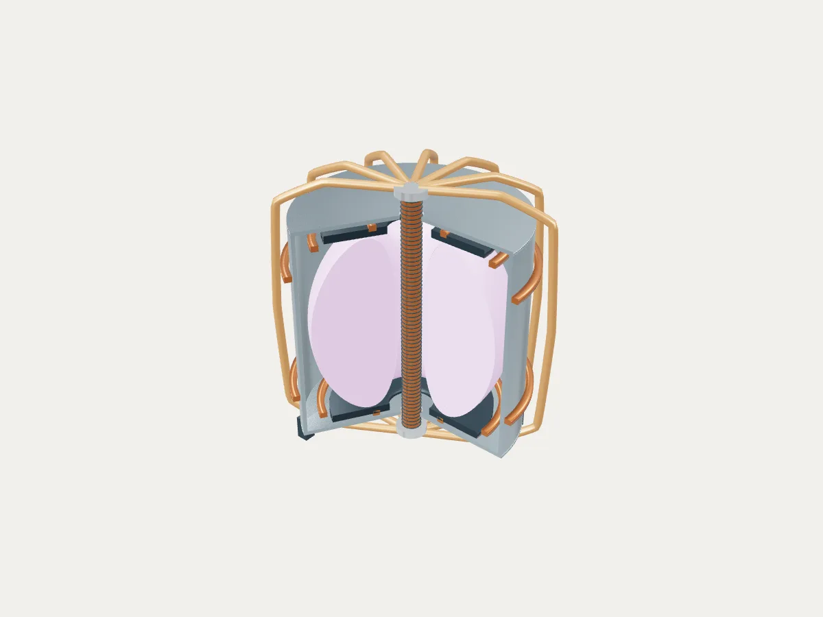
Original baseline machine cutaway, with center column and outer coils. This reference poster does not change with workbench inputs; the section above shows the current study.Reference machine poster · current geometry is in the section above
SPATIAL ENVELOPES · NOT A SIMULATION

3D loads only when requested. The reference poster and current section remain available without WebGL.

Keep this design point

Every file describes these inputs, including any overlap. Geometry is an authored spatial envelope, never certified CAD or solver input.

OBJ uses metres and Y up, with separate named objects for plasma, column, vessel pieces and non-material reserves. Touching vessel solids are not fused. No coil winding or plant equipment is exported.

What the reference sweep found

A fixed study spans 2,310 design points: 21 major radii (0.80–1.30 m), 11 column radii (0.10–0.30 m) and five inboard reserves (0, 0.04, 0.10, 0.20 and 0.30 m), under two vessel rules. Minor radius, shaping, vertical vessel size and other reserves stay at their baseline values. This study is independent of the editable point above.

Geometric classifications, not physically viable reactors
Vessel ruleSpace remainsContactOverlapSpace remains under adverse inputs
Fixed inner radius · 1.64 m32 / 11553112012 / 1155
Inner radius grows with R · R+a+0.14 m727 / 115513415687 / 1155

A 200 mm inboard reserve cannot fit with the baseline column, minor radius and fixed vessel while retaining the 100 mm outboard reserve: R would need to be at least 0.99 m and at most 0.89 m. The larger-envelope preset uses R=1.05 m and a 1.84 m vessel inner radius, leaving 60 mm inboard and 40 mm outboard. It is a spatial candidate, not an optimized reactor.

Method and evidence limits

boundary
R(t) = R0 + a cos(t + asin(δ) sin(t)); Z(t) = κ a sin(t), 0 ≤ t < 2π.
metrics
720 equally spaced boundary samples. Section area by signed polygon area; volume = 2π times the polygon first moment about the vertical axis; surface area from revolving each boundary segment.
clearances
Exact radial and vertical envelope extrema for the allowed shape range, with signed margins after subtracting each authored reserve. No surface-to-surface distance or coil clearance is inferred.
mesh
192 poloidal samples for plasma, 96 azimuthal segments; shared seam and axis vertices, outward triangle winding. Each named volume is closed independently. Touching vessel solids are not boolean-fused.
coordinate System
Metres; right-handed Cartesian X,Y,Z; Y vertical with Y=0 at the plasma midplane. Section coordinates are cylindrical radius R and height Z; conversion is [R cos φ, Z, R sin φ].
bounds
Finite exploratory limits, not physics or engineering limits; 1 < R/a ≤ 2, at most six decimal places per input and an inner plasma radius of at least 0.0001 m to avoid degenerate mesh exports.
  • Geometric space only. A positive margin is not engineering approval.
  • No magnetic equilibrium, plasma performance, neutron transport, thermal load, stress, cooling or tritium breeding calculation.
  • No TF return, PF winding pack, solenoid, divertor leg, port or maintenance-access fit is checked. The column is an aggregate envelope.
  • Published experimental radii are evidence for the baseline plasma scale only. All vessel, column, reserve and range choices are authored.
  • Reserves are hypothetical space, not material volumes; no inboard blanket or power-plant output is asserted.
  • The original family illustration is unchanged. This study uses Z=0 at the plasma midplane, rather than the illustration’s floor datum.

Primary references

  1. R. Scannell and teams · UKAEA-CCFE-CP(23)43

    MAST Upgrade: R = 0.85 m, a = 0.65 m; reported strongly shaped plasmas with elongation around 2.2. These inform the plasma envelope, not the engineering dimensions.

  2. J. Milnes et al. · MAST Upgrade — Construction Status (2015)

    Center-column coils, toroidal-field upgrades and divertor construction establish the component roles. The displayed contours, routing and counts are authored.

  3. UKAEA · MAST Upgrade facility

    Experimental plasma-exhaust research and development toward future fusion machines; not evidence of an operating electricity-producing plant.

  4. UKAEA · PROCESS spherical tokamak documentation

    Context for centrepost and low-aspect-ratio engineering constraints. No PROCESS run, optimization or power-plant validation was performed for this concept.

  5. S. I. Muldrew et al. · Conceptual design workflow for the STEP Prototype Powerplant (2024)

    Motivates staged spatial, equilibrium and engineering assessment. No STEP dimensions, operating point or performance target is used in this experimental-scale study.