INERTIAL CONFINEMENT FUSION
Extraordinary hardware.
One target at the centre.
Begin with the complete fusion plant. Follow the systems inward to the chamber, the fuel capsule, and the microscopic features that connect them.
You engineer the hardware.
We connect the work that makes it possible.
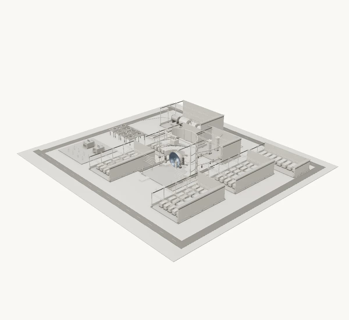
01 / THE WIDER SYSTEM
A complete plant. A connected engineering problem.
Power conversion, cooling, and electrical systems surround the fusion heat source. This campus is a conceptual setting for the target reference we are approaching.
How do component choices connect across the plant?
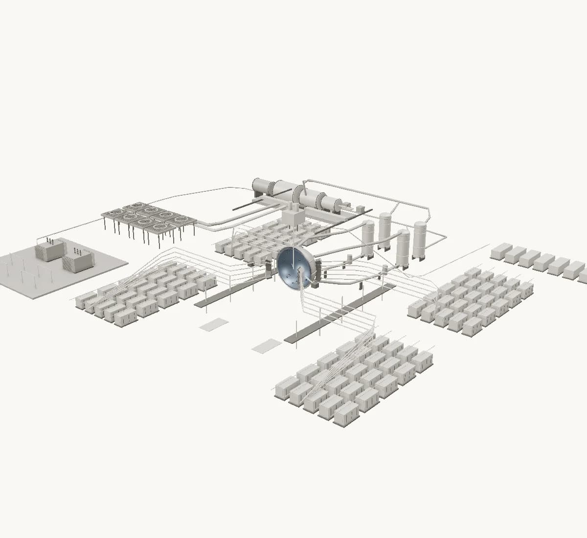
02 / MOVE INWARD
Follow the heat path back to its source.
Thermal systems connect the chamber to heat exchange and power conversion. Their placement and working conditions remain illustrative.
What does the chamber demand of the systems around it?
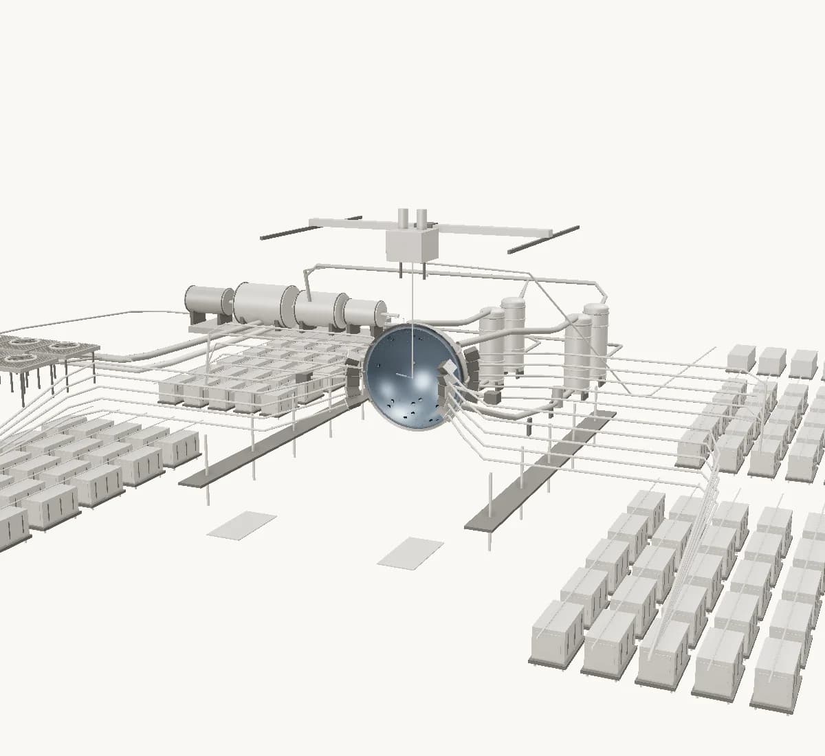
03 / LASER DELIVERY
Every optical path leads toward the target.
Laser hardware and final optics surround the chamber. The system relationships shown here are conceptual; the target detail ahead uses a published experimental reference.
How do alignment and optical tolerances reach the target?
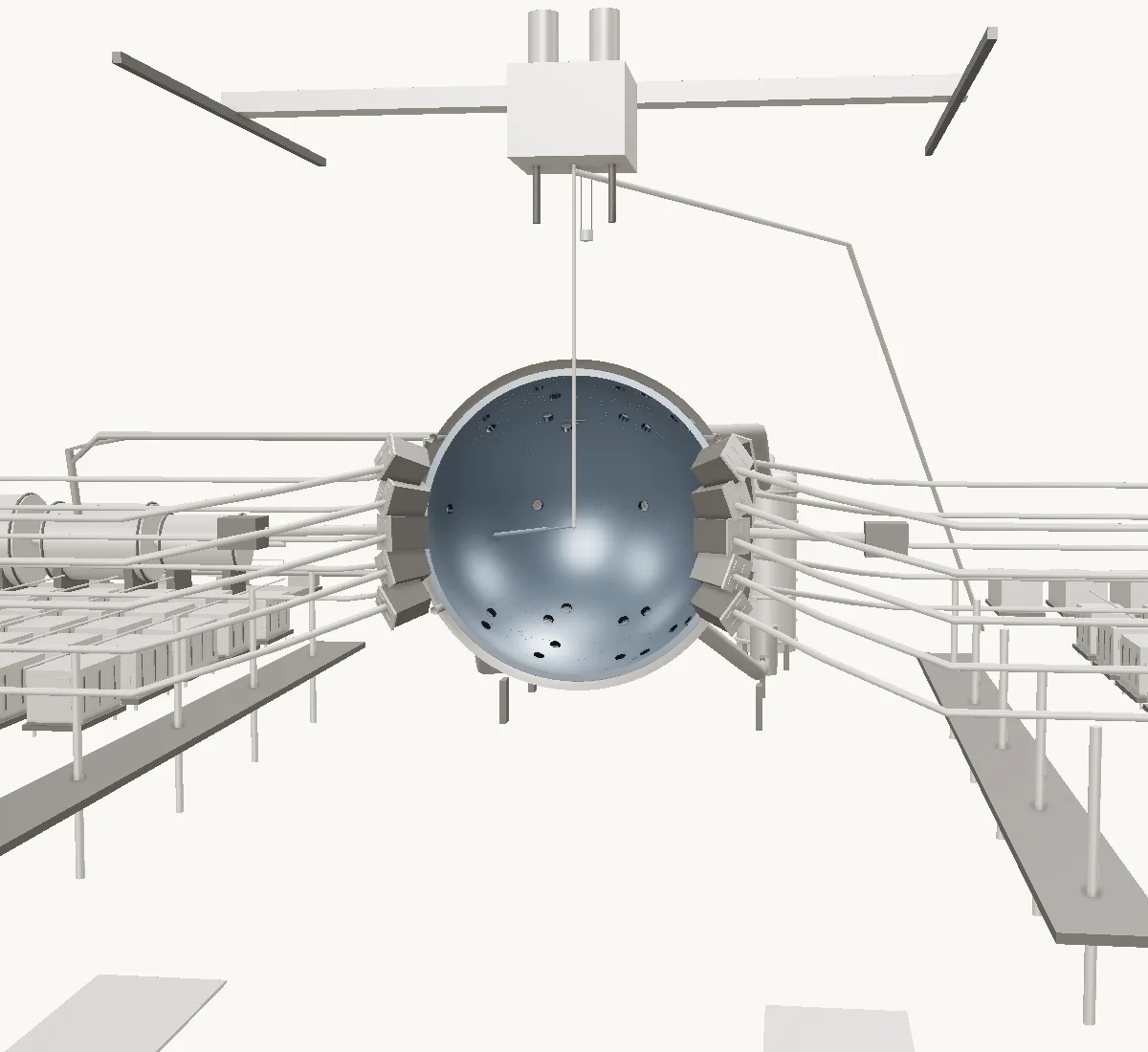
04 / THE CHAMBER
The chamber surrounds a millimetre-scale target.
Keep the target at the centre as the chamber recedes. The plant and chamber are illustrative context, with their assumptions recorded separately from the experimental target dimensions.
Which interfaces connect chamber-scale hardware to the target?
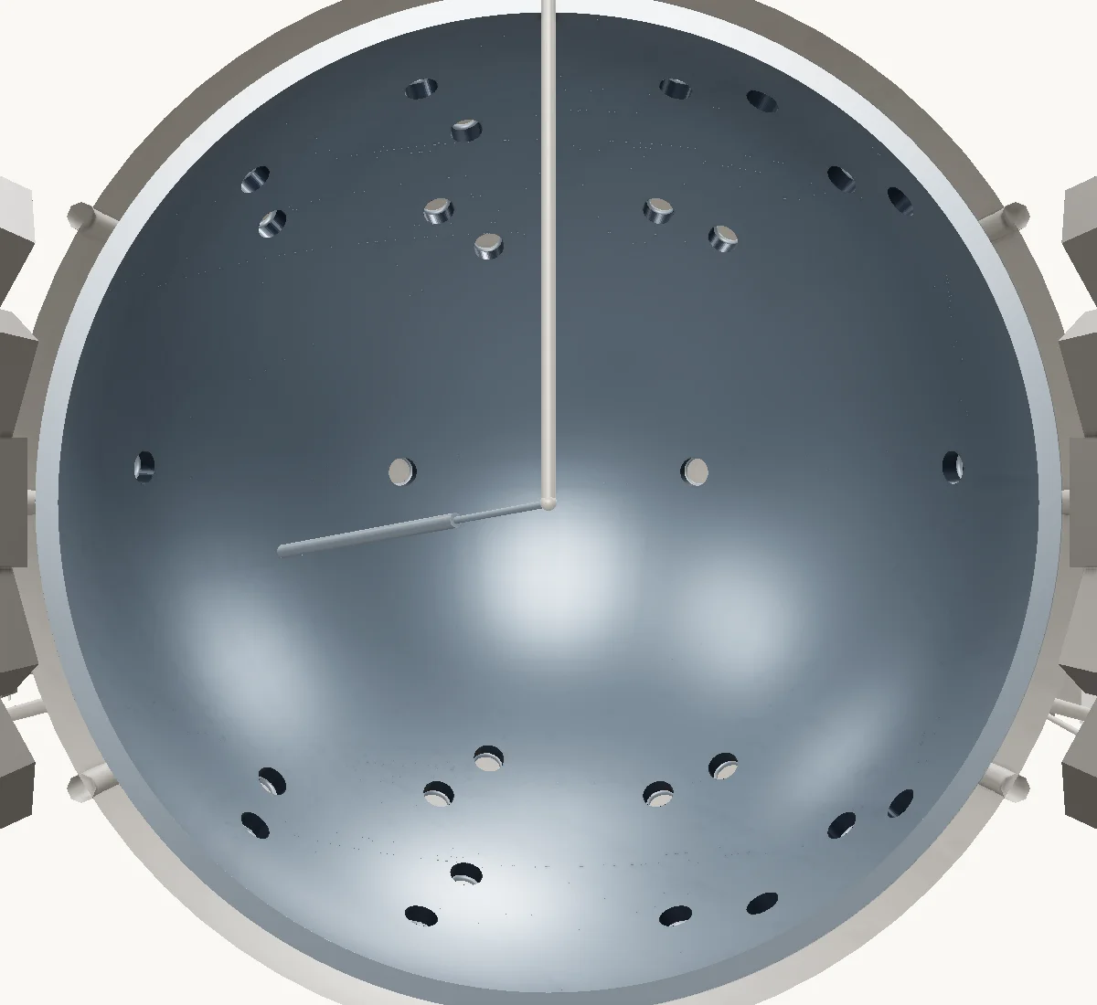
05 / THE TARGET
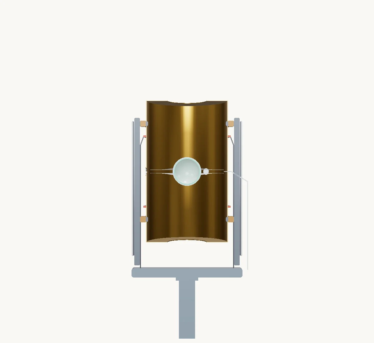
Inside the hohlraum. Around the fuel capsule.
A source-backed reconstruction replaces the conceptual target marker. The hohlraum, capsule, and support structures retain physical dimensions. Unresolved exterior hardware is estimated.
Which dimensions are published, and which geometry is inferred?
06 / THE CAPSULE
Inside the capsule. Layer by layer.
A diamond shell surrounds frozen fuel and a central gas region. The cutaway reveals the documented layers without enlarging them relative to the rest of the target.
How do the capsule layers and the fill junction meet?

07 / THE FINEST DETAIL
The smallest detail. Still part of the whole.
The journey ends at the capsule surface and its microscopic fill-tube junction. Smooth geometry expresses nominal dimensions, not measured roughness or a simulated implosion.
How does evidence at this scale connect back to the engineering of the plant?

THE MACHINE IS ONLY HALF THE STORY
A connected plant.
Disconnected teams?
We can change that.
Optics in one tool. Neutronics in another. Thermal models on a cluster. Structural results in someone else’s folder.
The hard part is keeping all that expertise connected as the design changes.
Morton Labs is the infrastructure and control plane for complex engineering.
Keep your tools.
Build around the physics codes, compute environments, and engineering methods your team knows and trusts.
Connect the work.
Coordinate disciplines, data transfers, and simulation campaigns. Make the interfaces explicit and reviewable.
Keep the evidence.
Trace results to the inputs, versions, and decisions that produced them. Give every team a common record.
YOUR EXPERTISE. MULTIPLIED.
Thousands of simulated experiences.
One engineering memory.
Let your team focus on the hardware. Use AI to coordinate approved tools, explore alternatives, and turn fragmented outputs into a body of engineering evidence.
How does the first wall respond across operating scenarios?
Your team sets the requirements. AI helps select approved tools and prepare the workflow. Engineers review the assumptions and approve the work.
Many scenarios.
A shared body of evidence.
Vary geometry, loads, and materials. Compare the spread. Carry what you learn into the next design.
- Inputs
- Geometry revision + material definition
- Execution
- Tool version · environment · configuration
- Outputs
- Load histories + component response
- Governance
- Ownership · access controls · review history
- Connected to
- Requirements → CAD revision → next workflow
Illustrative record structure. No live runs or measured results are shown.
Tool names illustrate workflows teams may bring. Availability, adapters, coupling methods, and validation are defined for each engagement.
THE WHOLE SYSTEM, IN YOUR HANDS
From the whole plant.
Into the target.
Follow the target from the wider plant to the chamber, capsule, and microscopic fill-tube junction.
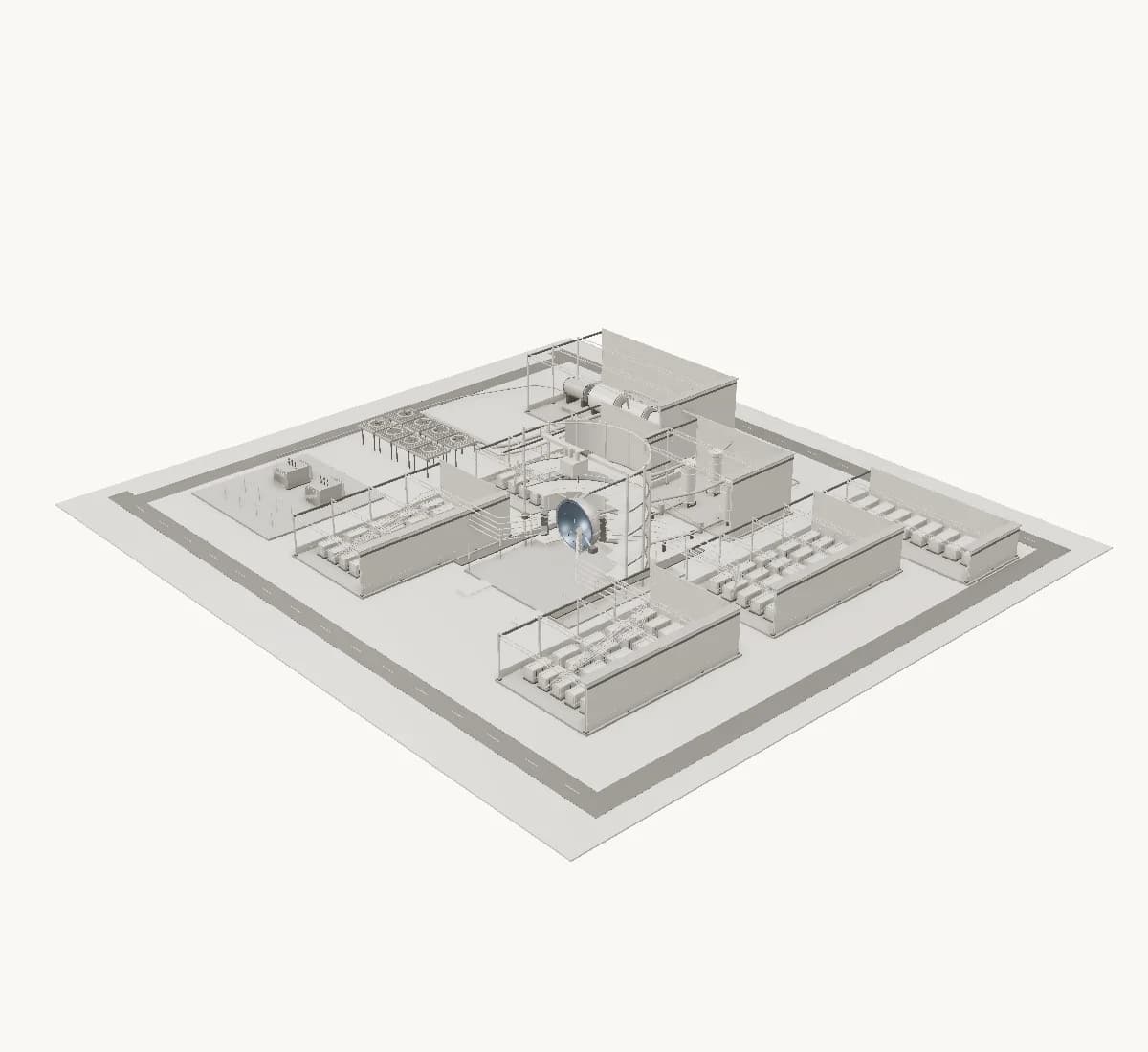
A still view is available. Load 3D when you’re ready.
Whole plantMetres at focus plane
About this model & its evidence
Adapted from the Fusion Atlas procedural plant concept. Component placement, dimensions, material appearance, and process paths are assumed for explanation. The beam and neutron graphics are conceptual overlays. They are not calculated fields, operating results, manufacturing CAD, or validated simulation geometry. No commercial plant performance is implied.
Read the model notes ↗ · Reported reference claims remain in the source evidence ledger; this target detail uses a published experimental reference within the illustrative plant.
ENGINEERING THAT STAYS WITH THE HARDWARE
From the first design
to a living digital twin.
The engineering record should keep growing after a component leaves the design environment.
Connect design intent and simulation history with test evidence, commissioning data, and operational measurements. Build toward monitoring systems that help teams understand change, investigate deviations, and plan the next decision.
Talk through your lifecycle ↗Design
Requirements, geometry, and assumptions
Simulate & validate
Campaigns connected to test evidence
Build & commission
As-built records and baseline measurements
Monitor & improve
Operational data informs the next model
BUILT FOR COMPLEX ENGINEERING
You build what comes next.
We connect what gets you there.
From advanced energy to any system where physics, hardware, and teams have to work as one.