Gas-cooled reactor.
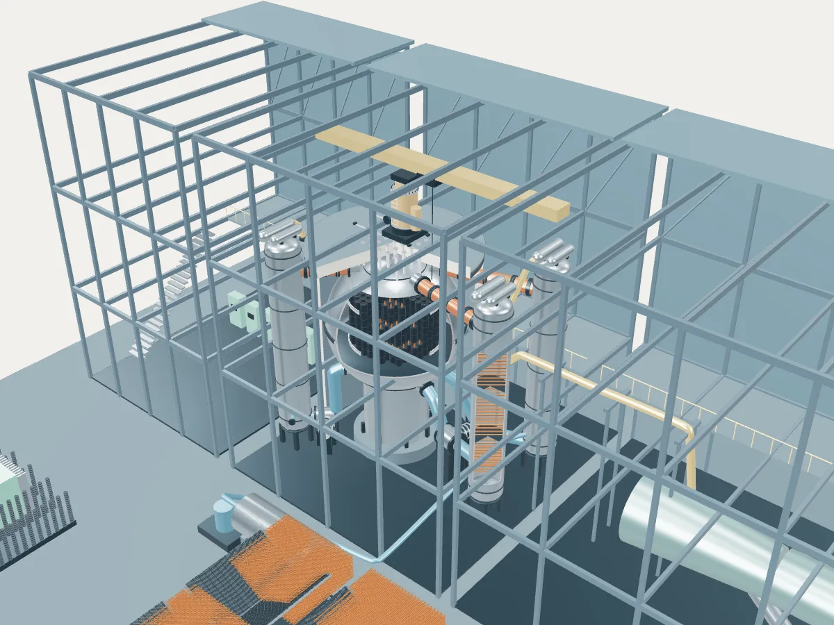
The gas-cooled reactor reference plant concept in 3D. Open a site from the globe, or from the list beside the view, to see its real numbers next to it.
 REFERENCE CONCEPT · NOT A SIMULATION
The gas-cooled graphite reactor reference plant.
The family’s reference concept, not any one station. The model illustrates a gas-cooled reactor concept, with the generic layout every design in the plant library shares: the reactor island, a turbine hall, air-cooled condensers and a grid connection. It does not show a real station's buildings, number of units, cooling or equipment.
The concept follows the early UK stations, with a steel vessel and the boilers outside it. The later Magnox stations at Oldbury and Wylfa, and most French UNGG reactors, used prestressed concrete vessels instead, some with the boilers inside, and the UK stations mostly ran two reactors where the concept shows one.
Carbon dioxide blown up through vertical channels in a graphite core carries heat away from natural-uranium metal fuel and leaves the steel pressure vessel at about 360 °C. Large ducts take the hot gas to separate tall boilers, where it raises steam, and gas circulators blow the cooled gas back into the bottom of the vessel.
- Fuel
- Natural uranium metal in magnesium-alloy cans
- Reaction
- Splitting heavy nuclei
- Energy transfer
- Carbon dioxide gas to separate boilers
Gas-cooled reactor
Carbon dioxide cools natural-uranium metal fuel in a graphite core. The first generation of British and French power stations, now all retired.