Hinkley Point.
2 EPR units at Hinkley Point, beside the EPR plant concept. The 3D model shows how the EPR design works; it is not Hinkley Point's actual layout.
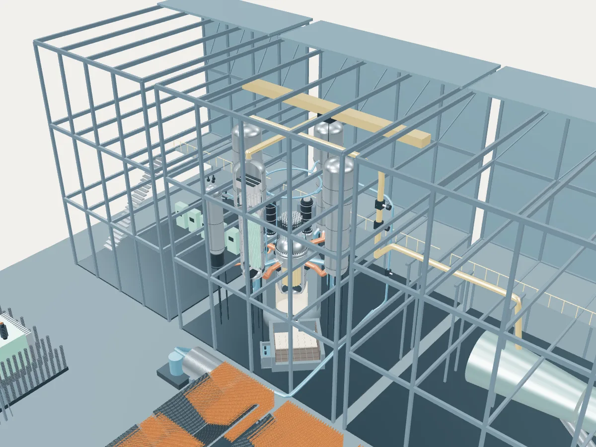 DESIGN CONCEPT · NOT A SIMULATION
The EPR plant concept.
The EPR design’s concept, not Hinkley Point. The model shows how an EPR plant works, drawn from the design’s public description, in the generic layout every design in the plant library shares: the reactor island, a turbine hall, air-cooled condensers and a grid connection. It does not show Hinkley Point's buildings, number of units, cooling or equipment.
The concept follows the standard EPR described to the IAEA, rated at 4,590 MWt and 1,650 MWe net and already revised with feedback from the Olkiluoto 3 and Flamanville 3 builds; the UK EPR assessed in Britain, based on Flamanville 3, was described at 1,600 to 1,660 MWe net, so units differ in rating and detail. The four loops are drawn at 0.45 scale in the plant library’s shared building frame, turned so the camera looks between two of them, and the double containment is left out to show the loops and the core catcher.
A large pressurized water reactor of about 1,650 MWe. Water at 15.5 MPa carries heat from a 241-assembly core through four loops, each with a vertical U-tube steam generator and a pump; an axial economizer in each generator sends the feedwater to the cold side of the tube bundle, which raises the steam pressure. If a core ever melted through the vessel, the melt would gather in the reactor pit, then flow through a melt plug into a spreading compartment beside it, where water from a tank inside the containment floods and cools it.
- Fuel
- Uranium dioxide or mixed-oxide assemblies
- Reaction
- Splitting heavy nuclei
- Energy transfer
- Four pressurized-water loops to steam generators
Pressurized water reactor
Water held at around 155 bar stays liquid as it carries heat from the core to steam generators, where a second loop boils. The most common reactor on Earth.
The EPR by its published numbers.
Each figure is the design’s own, as its source publishes it, with the page it is on. They describe the design, not any station: built units may be uprated, and the station’s own capacities are in its unit table. Nothing here is computed.
| Thermal power | 4,590 MWtIAEA ARIS status report, Table 2, Fuel/Core, p. 11 |
|---|---|
| Gross electric output | 1,770 MWeIAEA ARIS status report, §1 Overview, p. 1 |
| Net electric output | 1,650 MWeIAEA ARIS status report, §1 Overview, p. 1; Table 2, p. 10 |
| Fuel assemblies | 241IAEA ARIS status report, Table 2, p. 11; §5.2, p. 23 |
|---|---|
| Assembly lattice | 17 × 17, squareIAEA ARIS status report, Table 1, p. 9; §5.2, p. 24 |
| Fuel rods per assembly | 265 (with 24 guide tubes)IAEA ARIS status report, §5.2, p. 24 |
| Active core height | 4.2 mIAEA ARIS status report, Table 2, Reactor Core, p. 14 |
| Control assemblies | 89 rod cluster control assembliesIAEA ARIS status report, §5.2, p. 24 |
| Enrichment | 4.95 %IAEA ARIS status report, Table 2, Fuel/Core, p. 11 (≤ 5.0 wt% U-235 in §5.2, p. 24) |
| Refuelling cycle | 24 monthsIAEA ARIS status report, Table 2, Fuel/Core, p. 11 |
| Coolant loops | 4IAEA ARIS status report, §5.1 Primary circuit, p. 18 |
|---|---|
| Steam generators | 4, vertical U-tube with axial economizerIAEA ARIS status report, Table 2, p. 11 (U tubes with axial economizer); §5.1, p. 21 (vertical U-tube); p. 39 (the four steam generators) |
| Reactor coolant pumps | 4, vertical single-stage shaft-sealIAEA ARIS status report, Table 1, p. 8; §2.4.5, p. 22 |
| Primary pressure | 15.5 MPaIAEA ARIS status report, Table 2, Plant Infrastructure, p. 10 |
| Core inlet temperature | 295.2 °CIAEA ARIS status report, Table 2, p. 10 |
| Core outlet temperature | 330 °CIAEA ARIS status report, Table 2, p. 10 |
| Steam pressure | 7.72 MPaIAEA ARIS status report, Table 2, Nuclear System, p. 13 |
|---|---|
| Steam flow | 2,604 kg/sIAEA ARIS status report, Table 2, Nuclear System, p. 13 |
| Feedwater temperature | 230 °CIAEA ARIS status report, Table 2, Nuclear System, p. 14 |
| Reactor vessel diameter (inside or outside not stated) | 4,870 mmIAEA ARIS status report, Table 2, NSSS largest component diameter, p. 10 |
|---|---|
| Reactor vessel length | 13,083 mmIAEA ARIS status report, Table 2, NSSS largest component length, p. 10 |
| Reactor vessel wall | 250 mmIAEA ARIS status report, Table 2, NSSS largest component thickness, p. 11 |
| Containment | Double: prestressed concrete inner wall with a steel liner, reinforced concrete outer wallIAEA ARIS status report, §4 Containment, p. 17 |
| Design life | 60 yearsIAEA ARIS status report, Table 2, Plant Infrastructure, p. 9 |
Where the EPR’s heat goes.
One unit at its design rating, from the published figures above. Most of the reactor’s heat leaves through the condenser to the cooling water or air; the rest becomes electricity, some of which runs the plant itself. A figure marked “derived” is plain arithmetic on published ones; nothing is simulated.
- Reactor heat
- 4,590 MWtIAEA ARIS status report, Table 2, Fuel/Core, p. 11
- Gross electricity
- 1,770 MWeIAEA ARIS status report, §1 Overview, p. 1
- Net to the grid
- 1,650 MWeIAEA ARIS status report, §1 Overview, p. 1; Table 2, p. 10
- Used in the plant
- 120 MWeDerived: 1,770 MWe gross less 1,650 MWe net
- Heat rejected through the condenser
- 2,820 MWtDerived: 4,590 MWt of reactor heat less 1,770 MWe gross
- Net efficiency
- about 35.9 %Derived: 1,650 MWe net of 4,590 MWt
- 01 Heat source
- Reactor heat
- 4,590 MWtIAEA ARIS status report, Table 2, Fuel/Core, p. 11
- Primary pressure
- 15.5 MPaIAEA ARIS status report, Table 2, Plant Infrastructure, p. 10
- Core inlet to outlet
- 295.2 → 330 °CIAEA ARIS status report, Table 2, p. 10
- 02 Steam
- Steam generators
- 4, vertical U-tube with axial economizerIAEA ARIS status report, Table 2, p. 11 (U tubes with axial economizer); §5.1, p. 21 (vertical U-tube); p. 39 (the four steam generators)
- Steam pressure
- 7.72 MPaIAEA ARIS status report, Table 2, Nuclear System, p. 13
- Steam flow
- 2,604 kg/sIAEA ARIS status report, Table 2, Nuclear System, p. 13
- 03 Turbine and generator
- Gross electricity
- 1,770 MWeIAEA ARIS status report, §1 Overview, p. 1
- 04 Cooling and return
- Heat rejected
- 2,820 MWtDerived
- Feedwater temperature
- 230 °CIAEA ARIS status report, Table 2, Nuclear System, p. 14
- 05 Grid connection
- Net to the grid
- 1,650 MWeIAEA ARIS status report, §1 Overview, p. 1; Table 2, p. 10
- Used in the plant
- 120 MWeDerived
- Net efficiency
- about 35.9 %Derived
Hinkley Point’s 2 EPR units at design rating
Together they would take 9,180 MWt of heat from their reactors and reject 5,640 MWt to their cooling. Their own published net capacities add to 3,260 MWe, if all were running.
Hinkley Point as one power plant.
Every unit on the site, from the atlas’s unit records: each reactor drives its own generator, which feeds the station’s switchyard and the grid. This is a schematic of how the units connect, not the station’s layout; the atlas records no buildings, cooling, switchyard arrangement or grid voltage.
- Under construction · 2
- Shut down · 4
- On this page
- Operating
- None
- Being built or planned
- 2 units · 3,260 MWe net
- Shut down
- 4 units · 1,750 MWe net
- Plant concepts here
- EPR (2) · GCR reference (2) · AGR reference (2)