HPR1000.
The HPR1000 plant concept in 3D, drawn from the design's public description. Open a station from the list beside the view to see its real numbers next to it.
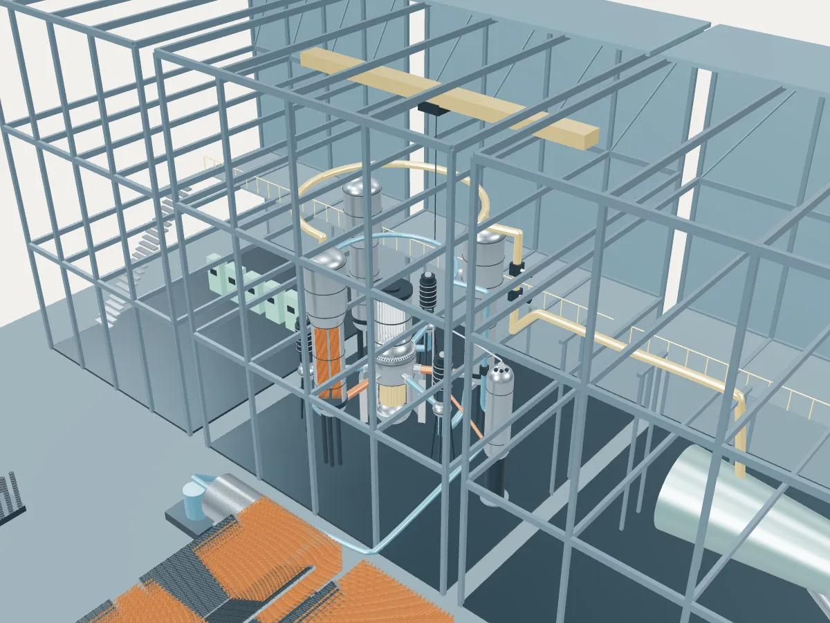 DESIGN CONCEPT · NOT A SIMULATION
The HPR1000 plant concept.
The HPR1000 design’s concept, not any one station. The model shows how an HPR1000 plant works, drawn from the design’s public description, in the generic layout every design in the plant library shares: the reactor island, a turbine hall, air-cooled condensers and a grid connection. It does not show a real station's buildings, number of units, cooling or equipment.
In 2013 CNNC and CGN agreed to merge their ACP1000 and ACPR1000+ designs as the HPR1000, but each builds its own version; both have the three-loop coolant system and the 177-assembly core and differ in safety-system details. The concept follows the IAEA status report’s version, with CNNC’s fuel and Zhangzhou 1 as reference plant, which removes heat passively from both the steam generators and the containment through tanks on the outer wall; the UK regulator assessed CGN’s version, built first at Fangchenggang 3, for which its summary names passive secondary heat removal and cavity injection as the added passive features. The concept is drawn at reduced scale without the double containment or its tanks.
A Chinese pressurized water reactor of 3180 MWt and about 1200 MWe, also called Hualong One. Water at 15.5 MPa leaves a core of 177 square fuel assemblies at 328 °C and runs out through three loops, each with a tall vertical steam generator, where it passes through U-shaped tubes and boils the water around them, and a vertical pump that returns it to the reactor. Active safety systems handle design-basis accidents, and passive ones back them up when all power is lost: heat removal from the steam generators and from the containment through tanks on the outer containment wall, and flooding of the reactor cavity to keep a damaged core inside the vessel.
- Fuel
- Uranium dioxide in square 17 × 17 assemblies
- Reaction
- Splitting heavy nuclei
- Energy transfer
- Three loops to vertical U-tube steam generators
Pressurized water reactor
Water held at around 155 bar stays liquid as it carries heat from the core to steam generators, where a second loop boils. The most common reactor on Earth.
The HPR1000 by its published numbers.
Each figure is the design’s own, as its source publishes it, with the page it is on. They describe the design, not any station: built units may be uprated, and the station’s own capacities are in its unit table. Nothing here is computed.
| Thermal power | 3,180 MWtIAEA ARIS status report, Table 2, p. 8; §5.2, p. 17 |
|---|---|
| Gross electric power (reference plant Zhangzhou 1) | 1,212 MWeIAEA ARIS status report, §1 Overview, p. 1; §5.5.1, p. 19 |
| Net electric power (reference plant Zhangzhou 1) | 1,126 MWeIAEA ARIS status report, §1 Overview, p. 1 |
| Turbine-generator speed | 1,500 rpmIAEA ARIS status report, §5.5.1, p. 18 |
| Fuel assemblies | 177IAEA ARIS status report, Table 2, p. 8; §5.2, p. 17 |
|---|---|
| Assembly lattice | Square, 17 × 17IAEA ARIS status report, Table 1, p. 6; §5.2, p. 17 |
| Fuel rods per assembly | 264IAEA ARIS status report, §5.2, p. 17 |
| Active core height | 3.658 mIAEA ARIS status report, Table 2, p. 11 |
| Equivalent core diameter | 3.228 mIAEA ARIS status report, Table 2, p. 11 |
| Control rod assemblies (UK HPR1000) | 68ONR, UK HPR1000 Step 4 summary, §7.1, ¶96, p. 23 |
| Refueling interval | 18 monthsIAEA ARIS status report, Table 2, p. 8; §5.2, p. 17 |
| Coolant loops | 3IAEA ARIS status report, Table 1, p. 6 |
|---|---|
| Steam generators | 3, vertical U-tubeIAEA ARIS status report, Table 1 (three loops), p. 6; Table 2, p. 8 |
| Reactor coolant pumps | 3IAEA ARIS status report, Table 1, p. 6 |
| Primary pressure at the core outlet | 15.5 MPaIAEA ARIS status report, Table 2, p. 7 |
| Core inlet temperature | 292.1 °CIAEA ARIS status report, Table 2, p. 7 |
| Core outlet temperature | 327.9 °CIAEA ARIS status report, Table 2, p. 7 |
| Steam pressure | 6.45 MPaIAEA ARIS status report, Table 2 (Nuclear System), p. 11 |
|---|---|
| Steam temperature | 280.3 °CIAEA ARIS status report, Table 2, p. 11 |
| Steam flow | 1,773 kg/sIAEA ARIS status report, Table 2, p. 10 |
| Feedwater temperature | 226 °CIAEA ARIS status report, Table 2, p. 11 |
| Reactor vessel inside diameter | 4,340 mmIAEA ARIS status report, Table 2 (largest component: the reactor vessel), p. 8 |
|---|---|
| Reactor vessel length (largest component) | 12,567 mmIAEA ARIS status report, Table 2, p. 8 |
| Containment | Double wall: prestressed inner wall with a steel liner (46.8 m inside diameter), reinforced-concrete outer wall (53 m)IAEA ARIS status report, §5.6, pp. 19–21 |
| Design life | 60 yearsIAEA ARIS status report, Table 2, p. 6 |
Where the HPR1000’s heat goes.
One unit at its design rating, from the published figures above. Most of the reactor’s heat leaves through the condenser to the cooling water or air; the rest becomes electricity, some of which runs the plant itself. A figure marked “derived” is plain arithmetic on published ones; nothing is simulated.
- Reactor heat
- 3,180 MWtIAEA ARIS status report, Table 2, p. 8; §5.2, p. 17
- Gross electricity
- 1,212 MWeIAEA ARIS status report, §1 Overview, p. 1; §5.5.1, p. 19
- Net to the grid
- 1,126 MWeIAEA ARIS status report, §1 Overview, p. 1
- Used in the plant
- 86 MWeDerived: 1,212 MWe gross less 1,126 MWe net
- Heat rejected through the condenser
- 1,968 MWtDerived: 3,180 MWt of reactor heat less 1,212 MWe gross
- Net efficiency
- about 35.4 %Derived: 1,126 MWe net of 3,180 MWt
- 01 Heat source
- Reactor heat
- 3,180 MWtIAEA ARIS status report, Table 2, p. 8; §5.2, p. 17
- Primary pressure at the core outlet
- 15.5 MPaIAEA ARIS status report, Table 2, p. 7
- Core inlet to outlet
- 292.1 → 327.9 °CIAEA ARIS status report, Table 2, p. 7
- 02 Steam
- Steam generators
- 3, vertical U-tubeIAEA ARIS status report, Table 1 (three loops), p. 6; Table 2, p. 8
- Steam pressure
- 6.45 MPaIAEA ARIS status report, Table 2 (Nuclear System), p. 11
- Steam temperature
- 280.3 °CIAEA ARIS status report, Table 2, p. 11
- Steam flow
- 1,773 kg/sIAEA ARIS status report, Table 2, p. 10
- 03 Turbine and generator
- Gross electricity
- 1,212 MWeIAEA ARIS status report, §1 Overview, p. 1; §5.5.1, p. 19
- Turbine-generator speed
- 1,500 rpmIAEA ARIS status report, §5.5.1, p. 18
- 04 Cooling and return
- Heat rejected
- 1,968 MWtDerived
- Feedwater temperature
- 226 °CIAEA ARIS status report, Table 2, p. 11
- 05 Grid connection
- Net to the grid
- 1,126 MWeIAEA ARIS status report, §1 Overview, p. 1
- Used in the plant
- 86 MWeDerived
- Net efficiency
- about 35.4 %Derived