VVER-440.
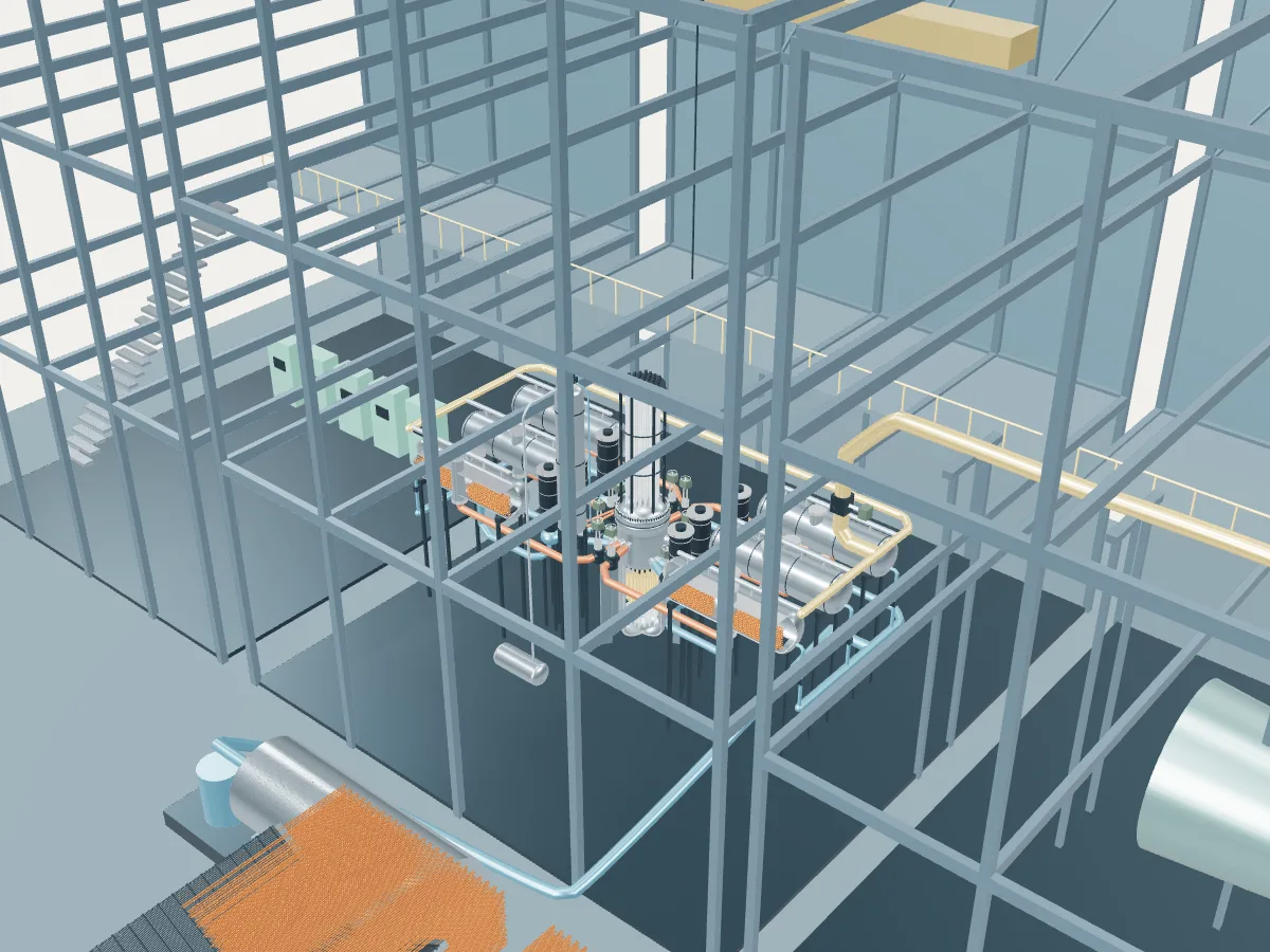
The VVER-440 plant concept in 3D, drawn from the design's public description. Open a station from the list beside the view to see its real numbers next to it.
 DESIGN CONCEPT · NOT A SIMULATION
The VVER-440 plant concept.
The VVER-440 design’s concept, not any one station. The model shows how a VVER-440 plant works, drawn from the design’s public description, in the generic layout every design in the plant library shares: the reactor island, a turbine hall, air-cooled condensers and a grid connection. It does not show a real station's buildings, number of units, cooling or equipment.
The concept is the V-213, the most built VVER-440. The older V-230 shares the six loops and gate valves but has weaker emergency cooling and a confinement relieved through valves instead of the V-213’s pool-type pressure-suppression tower; neither confinement is drawn, and the loops are compressed to fit the plant library’s shared building frame.
A Soviet-designed pressurized water reactor of 1375 MWt and 440 MWe. Water at 12.2 MPa leaves the core at 295 °C and runs out through six loops, each with a horizontal steam generator, where the heat crosses horizontal tubes to boil the secondary water, and a vertical pump that returns it to the reactor. Two main gate valves on every loop can isolate it from the reactor, and the hexagonal core’s 37 control assemblies carry fuel below their absorbers. The V-213 version drawn here adds emergency cooling sized for the largest pipe break and a pressure-tight confinement with a bubbler-condenser tower.
- Fuel
- Uranium dioxide in hexagonal assemblies
- Reaction
- Splitting heavy nuclei
- Energy transfer
- Six loops to horizontal steam generators
Pressurized water reactor
Water held at around 155 bar stays liquid as it carries heat from the core to steam generators, where a second loop boils. The most common reactor on Earth.
The VVER-440 by its published numbers.
Each figure is the design’s own, as its source publishes it, with the page it is on. They describe the design, not any station: built units may be uprated, and the station’s own capacities are in its unit table. Nothing here is computed.
| Thermal power | 1,375 MWtGRS-92 assessment (1992), §2.1, p. 6; Table 2-1, p. 35 |
|---|---|
| Gross electric power | 440 MWeGRS-92 assessment (1992), Table 2-1, p. 35 |
| Net efficiency | 30 %GRS-92 assessment (1992), Table 2-1, p. 35 |
| Turbine speed (two turbines) | 3,000 rpmGRS-92 assessment (1992), Table 2-1, p. 36 |
| Fuel assemblies | 312 (349 positions with the 37 control assemblies)GRS-92 assessment (1992), Table 2-1, p. 35; §4.1.1, p. 43 |
|---|---|
| Assembly type | Hexagonal, with shroudGRS-92 assessment (1992), Table 2-1, p. 35 |
| Fuel rods per assembly | 126GRS-92 assessment (1992), Table 2-1, p. 35 |
| Fuel rod active length | 2,500 mmGRS-92 assessment (1992), Table 2-1, p. 35 |
| Core diameter | 2.88 mSÚJB national report (2016), Annex 1, p. 2/18 (Dukovany, reactor core) |
| Control assemblies | 37, double assemblies (absorber above a fuel section)GRS-92 assessment (1992), Table 2-1, p. 35; §4.1.1, p. 43 |
| Coolant loops | 6GRS-92 assessment (1992), §2.1, p. 6; Table 2-1, p. 36 |
|---|---|
| Steam generators | 6, horizontalGRS-92 assessment (1992), §2.2, p. 7; Table 2-1, p. 36 |
| Main coolant pumps | 6, vertical single-stage centrifugalGRS-92 assessment (1992), §2.1, pp. 6–7 |
| Primary system pressure | 12.2 MPaGRS-92 assessment (1992), Table 2-1, p. 35 |
| Reactor coolant flow | 42,000 m³/hSÚJB national report (2016), Annex 1, p. 2/18 (Dukovany, reactor cooling system) |
| Reactor inlet temperature | 265 °CGRS-92 assessment (1992), Table 2-1, p. 35 |
| Reactor outlet temperature | 295 °CGRS-92 assessment (1992), Table 2-1, p. 35 |
| Steam pressure (PGV-440) | 4.61 MPaIAEA-TECDOC-1668, Table 3.1, p. 17 |
|---|---|
| Steam temperature (PGV-440) | 258.9 °CIAEA-TECDOC-1668, Table 3.1, p. 17 |
| Steam flow per generator (PGV-440) | 125 kg/sIAEA-TECDOC-1668, Table 3.1, p. 17 |
| Feedwater temperature (PGV-440) | 164–223 °CIAEA-TECDOC-1668, Table 3.1, p. 17 |
| Vessel inside diameter | 3.542 mSÚJB national report (2016), Annex 1, p. 2/18 (Dukovany, reactor technical parameters) |
|---|---|
| Vessel height | 11.8 mGRS-92 assessment (1992), Table 2-1, p. 36 |
| Vessel cylinder wall | 140 (plus 9 mm cladding) mmSÚJB national report (2016), Annex 1, p. 2/18 (Dukovany, reactor technical parameters) |
| Confinement (V-213) | Pressure-resistant compartment system with a pool-type pressure suppression systemGRS-92 assessment (1992), §2.4, p. 10; §2.4.4, p. 14 |
Where the VVER-440’s heat goes.
One unit at its design rating, from the published figures above. Most of the reactor’s heat leaves through the condenser to the cooling water or air; the rest becomes electricity, some of which runs the plant itself. A figure marked “derived” is plain arithmetic on published ones; nothing is simulated.
- Reactor heat
- 1,375 MWtGRS-92 assessment (1992), §2.1, p. 6; Table 2-1, p. 35
- Gross electricity
- 440 MWeGRS-92 assessment (1992), Table 2-1, p. 35
- Net to the grid
- about 410 MWeDerived: the published net efficiency, 30 %, of 1,375 MWt
- Used in the plant
- about 30 MWeDerived: 440 MWe gross less about 410 MWe net
- Heat rejected through the condenser
- 935 MWtDerived: 1,375 MWt of reactor heat less 440 MWe gross
- Net efficiency
- 30 %GRS-92 assessment (1992), Table 2-1, p. 35
- 01 Heat source
- Reactor heat
- 1,375 MWtGRS-92 assessment (1992), §2.1, p. 6; Table 2-1, p. 35
- Primary system pressure
- 12.2 MPaGRS-92 assessment (1992), Table 2-1, p. 35
- Core inlet to outlet
- 265 → 295 °CGRS-92 assessment (1992), Table 2-1, p. 35
- Reactor coolant flow
- 42,000 m³/hSÚJB national report (2016), Annex 1, p. 2/18 (Dukovany, reactor cooling system)
- 02 Steam
- Steam generators
- 6, horizontalGRS-92 assessment (1992), §2.2, p. 7; Table 2-1, p. 36
- Steam pressure (PGV-440)
- 4.61 MPaIAEA-TECDOC-1668, Table 3.1, p. 17
- Steam temperature (PGV-440)
- 258.9 °CIAEA-TECDOC-1668, Table 3.1, p. 17
- Steam flow per generator (PGV-440)
- 125 kg/sIAEA-TECDOC-1668, Table 3.1, p. 17
- 03 Turbine and generator
- Gross electricity
- 440 MWeGRS-92 assessment (1992), Table 2-1, p. 35
- Turbine speed (two turbines)
- 3,000 rpmGRS-92 assessment (1992), Table 2-1, p. 36
- 04 Cooling and return
- Heat rejected
- 935 MWtDerived
- Feedwater temperature (PGV-440)
- 164–223 °CIAEA-TECDOC-1668, Table 3.1, p. 17
- 05 Grid connection
- Net to the grid
- about 410 MWeDerived
- Used in the plant
- about 30 MWeDerived
- Net efficiency
- 30 %GRS-92 assessment (1992), Table 2-1, p. 35