SUNIST-2.
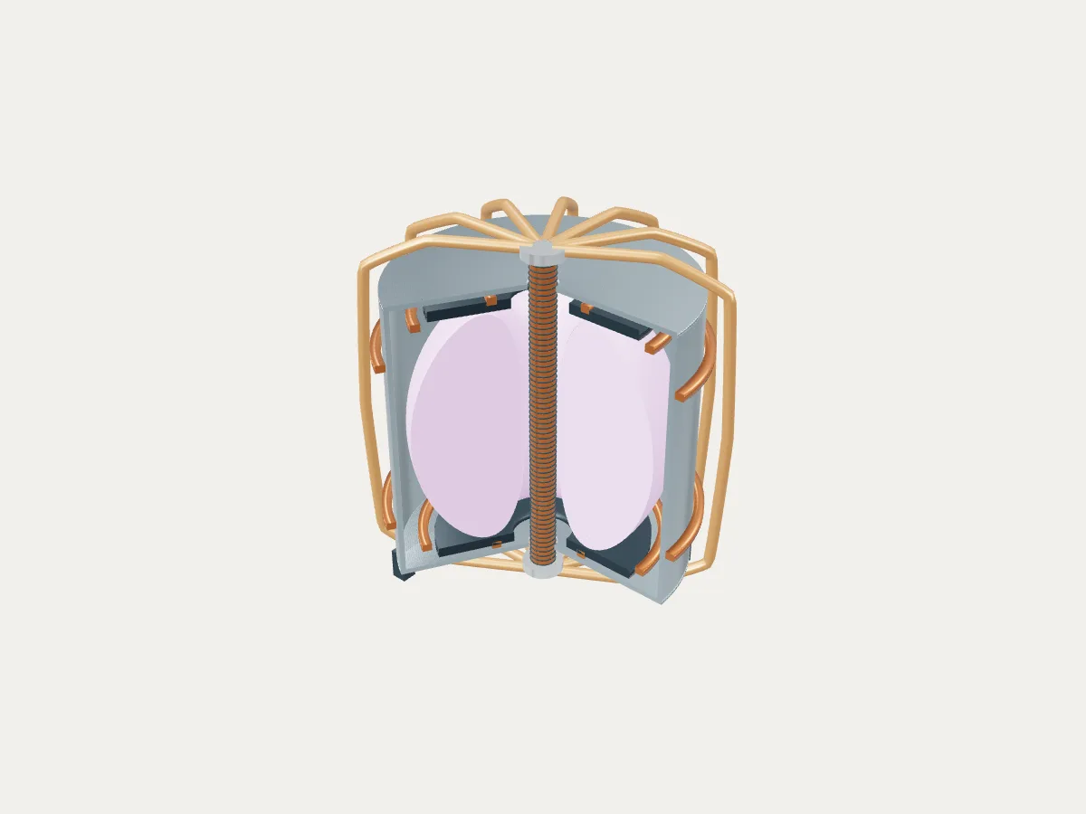
SUNIST-2 at Beijing, beside the spherical tokamak reference plant concept. The 3D model shows how the family works; it is not SUNIST-2's actual layout.
 REFERENCE CONCEPT · NOT A SIMULATION
Select a component here or pick it in 3D. Every component also has a text record below.
Enter the visual plant walkthrough Open the radial-build workbench
A smaller central opening.
The spherical plasma wraps tightly around its center column. The chosen plasma radii are published experimental inputs; the vessel, coil paths, supports and smooth plasma shape are teaching geometry.
| Quantity | Spherical | Conventional |
|---|---|---|
| Plasma major / minor radius | 0.85 / 0.65 · published inputs | 3.20 / 0.47 · stylized trace |
| Plasma R/a | 1.31 · derived | 6.81 · display trace only |
| Vessel outer diameter | 3.40 · illustrative | 9.24 · illustrative |
| Center-column radius | 0.14 · illustrative | 0.82 · illustrative |
Open the conventional tokamak concept
Experimental-device evidence
The published plasma radii and representative elongation set the low-aspect-ratio shape. Center-column, coil and divertor roles follow construction references. The six shaping rings and twelve returns shown here are simplified, not a reconstruction of the reference machine.
Hypothetical power-plant additions
Heat pickup, piping, exchanger, turbine, condensers and grid connection appear only in the optional plant view. No inboard breeding blanket is asserted to fit. Neutron shielding, tritium breeding, cooling, stresses, exhaust loads and net electricity remain unresolved.
Component records
These records remain available with no JavaScript or 3D support.
Plasma envelope · Experimental geometry basis
The broad, tall plasma wraps tightly around the center column. Published radii set its scale; the smooth boundary is authored and has no computed fields.
- Major radius R
- 0.85 m · Published / derived
- Minor radius a
- 0.65 m · Published / derived
- Aspect ratio R/a
- 1.31 (derived) · Published / derived
- Elongation
- 2.2 representative reported shaping · Published / derived
- Triangularity
- 0.30 authored · Illustrative
Center column · Machine
A slim column represents the tightly packed inner toroidal-field legs and solenoid. The exposed winding bands are teaching detail, not a coil design. Cooling, insulation and shielding are unresolved.
- Display radius
- 0.14 m · Illustrative
- Display height
- 4.0 m · Illustrative
TF return coils · Machine
Outboard return legs loop above and below the vessel to the narrow center column. Twelve paths are an authored teaching arrangement; the front returns are removed in cutaway.
- Return paths
- 12 representative · Illustrative
- Winding sections and routing
- Not engineering validated · Illustrative
PF coils · Machine
Six rings illustrate plasma-shaping coils. Their count and locations do not reconstruct the experimental machine’s full coil set.
- Ring count
- 6 representative · Illustrative
Vacuum vessel · Machine
A cylindrical vacuum enclosure surrounds the plasma and internal exhaust hardware. The front 120-degree sector lifts out of the teaching cutaway to reveal the column and cored-apple envelope.
- Outside radius
- 1.70 m · Illustrative
- Wall thickness
- 0.06 m · Illustrative
- Vertical envelope
- 0.35–3.75 m · Illustrative
Exhaust targets · Machine
Paired targets identify the exhaust regions. These simple rings do not reproduce a Super-X magnetic leg, strike point or heat-load distribution.
- Geometry
- Authored target rings · Illustrative
- Heat loads
- Not calculated · Illustrative
Heat pickup · Hypothetical power-plant addition
Outboard sectors suggest a possible heat-collection layer. No inboard breeding blanket or tritium self-sufficiency is established.
- Evidence boundary
- Hypothetical addition · Illustrative
- Performance
- Not calculated · Illustrative
Heat exchanger · Hypothetical power-plant addition
A generic heat exchanger links a hypothetical machine heat loop to the shared steam-cycle illustration. Fluid, duty and sizing are unknown.
- Evidence boundary
- Hypothetical addition · Illustrative
- Performance
- Not calculated · Illustrative
Heat loop · Hypothetical power-plant addition
Authored piping connects the outboard heat pickup and exchanger. This loop is not equipment demonstrated by the experimental geometry reference.
- Evidence boundary
- Hypothetical addition · Illustrative
- Performance
- Not calculated · Illustrative
Primary sources and their limits
- R. Scannell and teams · UKAEA-CCFE-CP(23)43
MAST Upgrade: R = 0.85 m, a = 0.65 m; reported strongly shaped plasmas with elongation around 2.2. These inform the plasma envelope, not the engineering dimensions.
- J. Milnes et al. · MAST Upgrade — Construction Status (2015)
Center-column coils, toroidal-field upgrades and divertor construction establish the component roles. The displayed contours, routing and counts are authored.
- UKAEA · MAST Upgrade facility
Experimental plasma-exhaust research and development toward future fusion machines; not evidence of an operating electricity-producing plant.
- UKAEA · PROCESS spherical tokamak documentation
Context for centrepost and low-aspect-ratio engineering constraints. No PROCESS run, optimization or power-plant validation was performed for this concept.
The spherical tokamak reference plant.
The family’s reference concept, not SUNIST-2. The model illustrates a spherical tokamak concept, with the generic layout every design in the plant library shares: the reactor island, a turbine hall, air-cooled condensers and a grid connection. It does not show SUNIST-2's buildings, number of units, cooling or equipment.
The default concept uses an experimental plasma scale with illustrative engineering contours. The optional heat-recovery equipment and shared plant are hypothetical. It is not a reconstruction of any device on the map, including larger planned superconducting power plants.
A low-aspect-ratio plasma wraps around a narrow center column. Separate toroidal-field return coils, shaping coils and a vacuum vessel reveal the machine architecture. The optional power-plant layer is hypothetical.
- Fuel boundary
- Experimental plasma basis; D–T power cycle hypothetical
- Reaction
- Magnetic confinement of light nuclei
- Energy transfer
- Hypothetical outboard heat pickup and separate steam circuit
Spherical tokamak
A low-aspect-ratio tokamak with a cored-apple plasma around a narrow center column. Compact geometry changes the confinement and engineering tradeoffs; it does not establish power-plant performance.