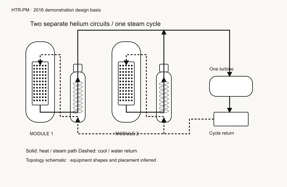
HTR-PM · 2016 demonstration design basis. Source-backed educational concept · not as-built CAD. Follow helium from the graphite core to a separate water and steam circuit.
This arrangement is one HTGR example. Other high-temperature and gas-cooled reactor designs differ.
NOT A SIMULATION
Generated schematic · inspect in 3D or read below
Schematic still · all descriptions remain available below.
Metres · illustrative equipment spacing Two modules, one turbine. Vessel envelopes, conventional equipment and layout are inferred.
Follow the heat
Choose a step to move between the system, vessel and pebble scales. The complete explanation is also below.
The complete explanation
The generated schematics, scale links, component descriptions and citations are available without 3D or JavaScript. A cutaway is an inspection aid; it is not an opening in the operating plant.
Start inside a pebble
Fission heat originates in fuel kernels. Buffer carbon, inner pyrocarbon, silicon carbide and outer pyrocarbon surround each kernel. The graphite matrix conducts heat to the pebble surface; coating thicknesses are not modeled. [S3]
Carry heat down the bed
Helium enters the upper plenum, descends among the pebbles and leaves through the central hot-gas duct. Arrows show direction only, not velocity or a calculated temperature field. [S2]
Exchange heat without mixing
Helium flows downward outside the steam-generator tubes as water rises inside them. The tube wall separates the fluids. Cooled helium rises outside the shroud to the blower, then returns through the coaxial duct annulus. [S2]
Join two steam supplies
Two reactor modules have separate helium circuits and steam generators. Their secondary steam supplies join at one turbine. Manifolds and the conventional power equipment are schematic. [S1]
Read the limits
This is one documented pebble-bed arrangement. Other HTGRs may use prismatic fuel or different system layouts. AGR, Magnox and gas fast reactors are separate families. This display does not calculate reactor performance or establish safety. [S4]
Components and evidence
Reactor pressure vessel
Pressure boundary around graphite internals. The 25 m tall, 6.4 m wide display envelope, head contour and supports are inferred.
Published active envelope: 3 m diameter × 11 m height. Enlarged sparse markers show the bed; they do not reproduce its packing or 420,000-pebble inventory.
Graphite surrounds the bed. Side-reflector coolant channels carry helium upward before it turns down through the core. Channel positions and reflector thickness are inferred.
From the blower: duct outer annulus → side-reflector channels → upper plenum. Return from the SG rises outside its shroud. Arrow placement and line thickness are illustrative.
Each module has its own once-through steam generator. Water rises inside the helical tubes while helium descends outside. Nineteen assembly positions are shown with one representative helix each.
The two steam generators feed one turbine. Feedwater returns to their lower ends. The common manifold, condenser and pipe routing are schematic. Water never joins the helium circuit.
The published pebble contains approximately 12,000 TRISO particles. Visible dots are enlarged sampled symbols, not a counted inventory or a particle-layer model. Coatings are described in the guide.
Published values describe the selected historical design basis; they are not simulation results. Source S2 uses different steam conditions; the concept retains S1’s values. The vessel envelope, exact channel positions, tube turns, supports, pipe bends and plant placement are inferred. Controls, shutdown systems, fuel sorting, shielding and auxiliary systems are not fully represented.
inferredRounded display envelope; not an accepted vessel specification
vessel Radius
3.2 m
inferredOuter envelope assumption
reflector Radius
2.6 m
inferredAuthored thickness
core Bottom
8 m
inferredDisplay elevation
module Pitch
14 m
inferredEquipment separation for inspection
sg Offset
8 m
inferredReactor-to-SG centre distance
sg Radius
1.7 m
inferredDisplay envelope
sg Top
16 m
inferredDisplay elevation; below core top
overview Pebble Radius
0.14 m
illustrativeEnlarged markers; sparse sample, not physical pebbles
particle Marker Radius
0.001 m
illustrativeEnlarged representative symbols; not particle dimensions
Sources for this reference
Public source citations identify the reference; they do not imply a partnership or endorsement. All geometry and schematics here are independently authored. No source figures are redistributed.
Two 250 MWth modules, one 210 MWe turbine; core 3 m diameter / 11 m height; helium 7 MPa and 250/750 °C; 60 mm pebbles; 420,000 pebbles per core; 19 helical tube assemblies per steam generator.
Historical design basis, not current operation or dimensional manufacturing drawings. HTML read; PDF redirect failed. Accessed 2026-11-06.
Cool helium returns through the duct annulus, rises through side-reflector channels, then descends through the bed. Hot helium leaves through the duct centre, descends outside SG tubes and returns upward outside the shroud. Feedwater rises inside tubes.
Its 13.9 MPa / 571 °C steam values differ from S1; not adopted. No transient results are reproduced. Accessed 2026-11-06.