Explore / inspect / follow the energy
A plant you can step into.
HTR-PM · 2016 demonstration design basis. A visual concept with authored hardware, material finishes and a guided fuel-to-grid story.
From the plant to a single fastener
Step inside the concept.
Explore equipment, inspect surfaces, and follow the energy story.
Procedural geometry · no downloads or account requiredThe still image and complete text tour are available before loading 3D.
The energy story
Fuel in. Electricity out.
Eight authored chapters · 64 seconds of storytelling, not plant time. Fuel, helium, water and electricity remain distinct.
Playback is off for reduced motion or data saving. Use chapter buttons or the timeline to inspect still states.
Markers stand for pebbles entering the bed and returning through a schematic handling loop. Fuel remains in the nuclear island.
Source relationship · S4What you are looking at
Source relationships.
Authored visual detail.
This is a visual interpretation of one documented pebble-bed arrangement, not the layout of every HTGR or gas-cooled reactor. The two-module relationship, core and fuel-pebble dimensions and separation of the helium and water circuits come from the reference sources.
Buildings, equipment placement, turbine internals, bolts, screws, threads, cooling bank and worn finishes are illustrative. Cutaways remove material for viewing. The isolated fuel specimen is moved outside the vessel. No wear, temperature, reaction rate, operating time or electrical output is calculated here.
Source-backed geometry and citations → · Separate reference calculations →
Accessible tour
Every stop, in words.
The still image, stop links and this explanation work without WebGL or JavaScript.
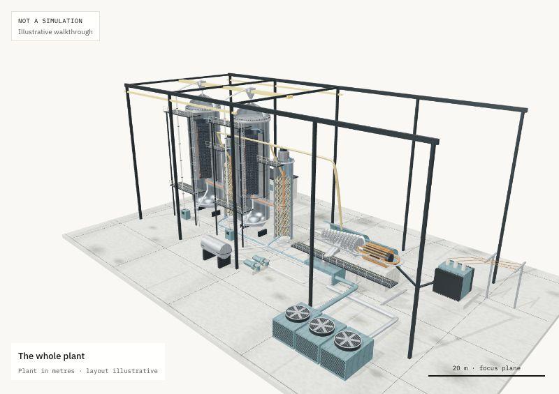
The whole plant
Two pebble-bed reactor modules deliver heat to two steam generators. One turbine and generator turn that heat into electricity.
Open walls reveal the equipment. Buildings, spacing, service platforms and conventional plant equipment are an authored arrangement, not the station layout.
Plant in metres · layout illustrative
Open this stop · Reference S1Fuel arrives as pebbles
Graphite fuel pebbles enter from above. An illustrative handling loop traces discharge, inspection and a possible return to the top. This is distinct from the sealed helium circuit.
Hoppers, sorter, transport route and drive hardware are teaching geometry. Actual handling and burnup decisions are not simulated.
Metres · transport route schematic
Open this stop · Reference S4Inside the pebble bed
Heat is released inside coated fuel particles within graphite pebbles. Helium passes down through the bed and carries heat away. The cutaway lets you look through the vessel and reflector.
The core envelope follows the 3 m diameter and 11 m height reference. The sparse, enlarged bed markers are not an actual packing or particle population.
Core Ø 3 m × 11 m · source dimensions
Open this stop · Reference S1Follow the helium
Hot helium leaves the lower core through the inner hot duct. After giving up heat in the steam generator, helium returns through the circulator and outer passage, then rises toward the top of the core.
The separated display paths make the coaxial duct and return leg legible. Duct bends, channel offsets and moving markers are illustrative.
Metres · flow markers enlarged
Open this stop · Reference S2Heat crosses a tube wall
Helium and water remain in separate circuits. Water rises inside the helical tubes; helium releases heat outside them. Steam leaves for the common turbine.
Nineteen representative coil positions echo the documented assembly arrangement. Tube turns, diameters and local supports are authored, not tube-by-tube CAD.
Metres · representative coils
Open this stop · Reference S2Steam becomes shaft work
Steam expands through the turbine and turns the common shaft. Open the casing to see representative rotor discs and blades.
The turbine blades, casing, fasteners and steam path are authored teaching detail. Rotation rate and blade count are visual choices.
Metres · internals illustrative
Open this stop · Reference S1The generator
The turbine shaft drives the generator. The exposed rotor and copper-coloured windings show the idea of mechanical-to-electrical conversion.
Windings and rotor are symbolic geometry; this view does not calculate electromagnetic fields, torque or electrical output.
Metres · generator illustrative
Open this stop · Reference S1Close the steam circuit
Exhaust steam reaches a condenser and returns to liquid. A separate cooling-water circuit carries rejected heat away.
The condenser shell, tube bundle and cooling connection are conventional explanatory equipment, not an as-built condenser design.
Metres · balance of plant inferred
Open this stop · Reference S1Rejected heat leaves the plant
This authored cooling bank makes the heat-rejection side of the cycle visible. Cooling water returns to the condenser after releasing heat to the surroundings.
The fan-bank choice is a visual placeholder. It does not identify the reference station’s cooling installation or predict water use.
Metres · cooling choice illustrative
Open this stop · Reference S1Water returns to the heaters
Condensate passes through an illustrative tank and pump set before returning as feedwater to the steam generators. The full visual loop now closes.
The display simplifies heaters, chemistry, valves and auxiliary branches. It is a process story, not a complete piping and instrumentation diagram.
Metres · simplified water circuit
Open this stop · Reference S2Power leaves the site
The generator feeds a transformer and switchyard. The outgoing conductors complete the visual journey from fuel to useful electrical energy.
Transformer cooling fins, bushings and switchyard are authored. Voltage levels, electrical protections and losses are not modeled.
Metres · electrical equipment illustrative
Open this stop · Reference S1Down to the fastener
Inspect a representative service-joint fastener: helical thread, hexagonal nut, washer and slotted cover screws. Zoom closely to see machining marks and cosmetic staining.
An authored 36 mm shaft example, not a specified reactor bolt. Wear is a visual art control, not measured corrosion or remaining service life.
Millimetres · assumed 36 mm shaft
Open this stopOne fuel pebble
An isolated 60 mm graphite sphere contains a 50 mm fuel zone. Enlarge the view to see a representative cut face and dispersed coated-particle symbols.
The specimen is moved outside the vessel for inspection. Particle symbols are sampled and enlarged; individual coating layers are not resolved.
Ø 60 mm · fuel zone Ø 50 mm
Open this stop · Reference S3Complete process story
From fuel to grid.
Shown in chapters for explanation. A plant’s processes overlap; this is not an operating procedure.
Load & recirculate
Markers stand for pebbles entering the bed and returning through a schematic handling loop. Fuel remains in the nuclear island. [S4]
Release heat
The bed brightens to represent heat release within the fuel. This is a visual cue, not a temperature field or a neutron calculation. [S1]
Move heat in helium
Helium carries heat down the bed and along the hot duct, then cools in the steam generator and returns. Moving dots stand for direction only. [S2]
Make steam
A new set of markers starts on the water side. Heat crosses the tube wall; helium and steam never mix. Steam heads to the shared turbine. [S2]
Turn the shaft
The shaft and representative rotor discs turn. The visual speed is chosen for legibility, not the machine operating speed. [S1]
Deliver electricity
The generator feeds the transformer and outgoing conductors. The markers describe the energy chain; they are not electrons traveling from the fuel. [S1]
Reject unused heat
Turbine exhaust condenses while a separate cooling circuit carries heat to the illustrative fan bank. These circuits are shown as separate equipment paths. [S1]
Return the water
Water returns through the condensate/feedwater equipment to the steam generators. The sequence stops here; a running plant would maintain continuous overlapping flows. [S2]