THTR.
1 HTGR unit at THTR, beside the high-temperature gas-cooled reactor reference plant concept. The 3D model shows how the family works; it is not THTR's actual layout.
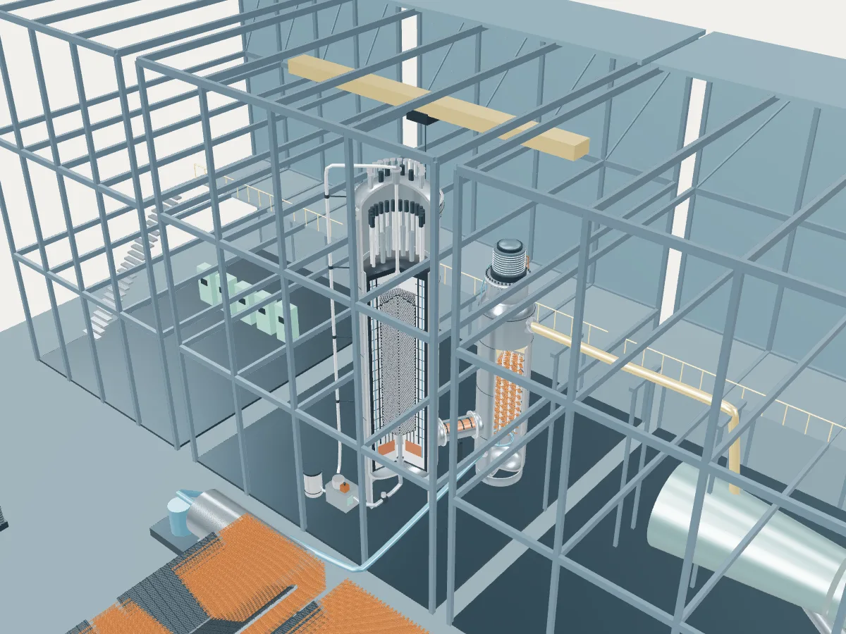 REFERENCE CONCEPT · NOT A SIMULATION
The high-temperature gas-cooled reactor reference plant.
The family’s reference concept, not THTR. The model illustrates a high-temperature gas reactor concept, with the generic layout every design in the plant library shares: the reactor island, a turbine hall, air-cooled condensers and a grid connection. It does not show THTR's buildings, number of units, cooling or equipment.
Shidao Bay runs two of these reactor modules into one shared turbine; the concept draws one module. Fort St. Vrain, Peach Bottom-1 and Japan’s HTTR are prismatic designs that hold their fuel in graphite blocks or rods instead of a bed of loose spheres, and Fort St. Vrain and THTR-300 housed the core and steam generators in one prestressed-concrete vessel rather than two steel vessels side by side.
Explore the documented two-module reference, vessel and fuel pebble →
Helium flows down through a tall bed of graphite fuel spheres, each holding thousands of ceramic-coated fuel particles, and leaves the core at about 750 °C. A coaxial duct carries the hot helium to a separate steam generator, where helical tube bundles raise steam, and the circulator on top of that vessel sends the cooled helium back to the reactor.
- Fuel
- Coated-particle fuel in graphite spheres
- Reaction
- Splitting heavy nuclei
- Energy transfer
- Helium primary circuit to a steam generator
High-temperature gas reactor
Helium removes heat from coated-particle fuel in graphite. Designs may use pebble beds or prismatic blocks. The linked two-module pebble-bed reference is one arrangement, not a model for every HTGR, AGR or gas-cooled reactor.
THTR as one power plant.
Every unit on the site, from the atlas’s unit records: each reactor drives its own generator, which feeds the station’s switchyard and the grid. This is a schematic of how the units connect, not the station’s layout; the atlas records no buildings, cooling, switchyard arrangement or grid voltage.
- Shut down · 1
- On this page
- Operating
- None
- Shut down
- 1 unit · 296 MWe net
- Plant concepts here
- HTGR reference (1)