Canada · Pressurized heavy water reactor

Pickering.

8 PHWR units at Pickering, beside the pressurized heavy water reference plant concept. The 3D model shows how the family works; it is not Pickering's actual layout.

Back to the globe at Pickering

Walk through the plant · fuel to grid →

Reactor · Capped geometric cutaway · metres, no hidden scaling. Shared plant equipment and placement are illustrative.

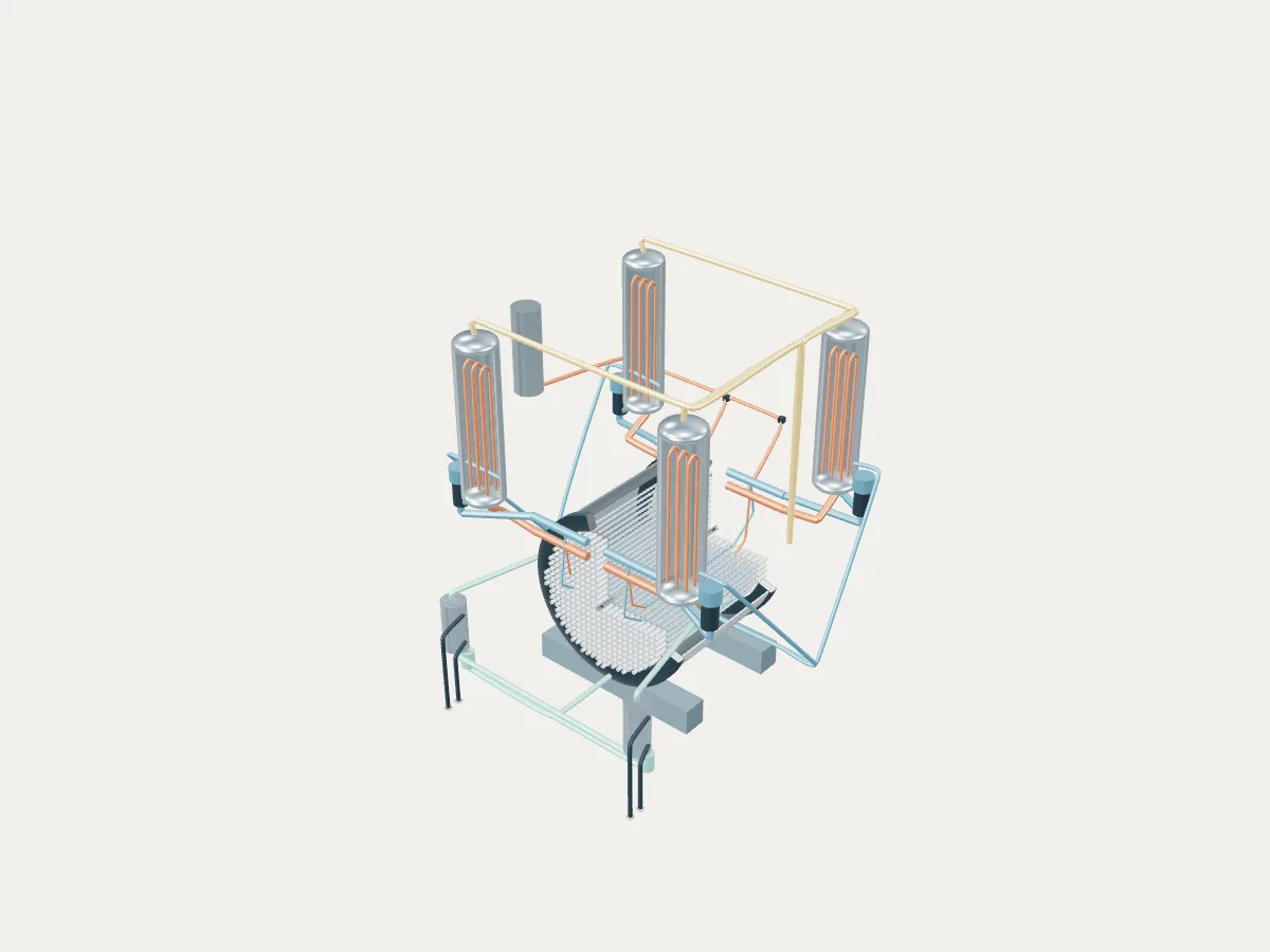
Reactor cutaway exposes horizontal channels inside the calandria, flanked by four steam generators and warm/blue primary paths, with a separate green moderator cooling circuit in front.REFERENCE CONCEPT · NOT A SIMULATION

Reference still · interactive view loads when available

Representative teaching geometry, never a station’s as-built layout. Pick a component below or in 3D. Every view and selection has a shareable URL. No physics solver has run.

Open the channel engineering workbench →

Moderator · Illustrative geometry

Calandria and end shields

Horizontal low-pressure moderator tank surrounding the channels. The moderator stays outside the calandria tubes. End shields and tank dimensions are illustrative envelopes; the site buildings are not a station layout.

Channel count
380; illustrative square-lattice occupancy (documented)
Tubesheet span
5.94 m (p.28); not full channel length (documented)
Calandria radius / wall
3.8 m / 0.08 m, assumed (illustrative)
Not shown
Reactivity devices, vault water, detailed shielding and containment (unknown)
CANDU 6 Technical Summary (May 2005), p.8

Primary heat transport · two figure-of-eight loops

  1. Fuel / pressurized D₂O in pressure tubes
  2. Outlet header
  3. Steam-generator primary U-tubes
  4. Pump and inlet header
  5. Opposite-direction core pass, second SG and pump

Warm outlets and blue returns. Each loop serves half the core. Representative feeders only.

Moderator · separate low-pressure D₂O

  1. Calandria outside calandria tubes
  2. Two moderator pumps
  3. Two moderator heat exchangers
  4. Return to calandria

Green paths. No material-flow connection to primary coolant or turbine. Service water takes heat across the exchangers and exits the model boundary.

Secondary · light water / steam

  1. Steam-generator secondary side
  2. Turbine
  3. Condenser
  4. Feedwater back to steam generators

Gold steam and blue feedwater. Shared turbine and air condensers are illustrative plant context, not reference-station equipment.

Channel boundaries · from inside to outside

  1. Fuel and primary coolant
  2. Pressure tube
  3. CO₂ gas annulus and spacers
  4. Calandria tube
  5. Cool moderator

The gas gap insulates the pressure tube. Tint, cutaways and source temperatures are explanatory cues, never computed fields.

Sources, assumptions and unresolved differences

CANDU 6, May 2005 baseline; not EC6. Metres, Y up, channel axis Z. mm × 0.001 = m. Temperatures °C; pressure basis explicit. No solver.

Assumptions and omitted detail

  • A01 · Plant / reactor. Shared building frames, turbine, air condensers and grid retain existing geometry. Calandria, shielding and equipment envelopes are illustrative, not as-built. Containment, vault water, fuelling machines, reactivity devices and safety systems are omitted.
  • A02 · Channel array. Choose 379 nearest noncentral square lattice positions plus one central detailed channel. Pitch 0.286 m and occupancy are assumed, not a loading map. Cutaway hides a sector of envelopes.
  • A03 · Representative channel. Pressure-tube wall and calandria-tube bore/wall now follow the separately identified 2001 supporting source. Pressure-tube/end-fitting lengths, end hardware, spacer positions and all tolerances remain unresolved or illustrative.
  • A04 · Paths. Topology follows pp.13–15. Routing, piping radii, representative feeders, header positions, pump shells and SG tube counts are illustrative. No velocities, thermal fields or equipment compatibility claimed.
  • A05 · Display. Warm primary outlets, blue primary returns, green moderator pipes, neutral service-water and gold secondary steam distinguish circuits. These are authored display colors, not results. Cut faces cap only the geometric shell section; cutaway is not an opening in operation.
  • A06 · Channel engineering packet. Nominal arithmetic is not a clearance acceptance criterion. Ring radii/phases, element end lengths, pad/plate profiles, spacer sections/positions and end-fitting envelopes are assumed. CAD solids omit pellets and sealing internals. Room-temperature dimensions do not predict hot, irradiated or sagged geometry.

Unresolved differences

  • C01. Rounded six-metre channel description (p.4) versus 5.94 m tubesheet span (p.28). Use 5.94 m for tubesheet span only; total pressure tube / fitting lengths assumed. These are not established as identical datums.
  • C02. 12 × 495.3 mm = 5943.6 mm, 3.6 mm longer than 5.94 m tubesheet span. Preserve both published numbers. Centre the 5.9436 m train; do not silently shorten bundles or claim a qualified axial stack.
  • C03. p.15 historical Point Lepreau gross/net 680/633 MWe versus current NB Power profile gross 715000 kW and introductory 660 MW without the same basis. No universal CANDU 6 electric output is assigned. Atlas site values remain their separately sourced data; never use this concept to revise station ratings.
  • C04. p.28 total PHTS flow 7.7 Mg/s and nominal per-channel 24 kg/s do not multiply to the same total across 380 channels. Do not derive a flow or heat balance from these labels; omit quantitative flow from the viewer. No silent reconciliation.
  • C05. PHWR family includes other CANDU designs and non-CANDU PHWRs; p.15 lists different channel counts for Bruce/Darlington. CANDU 6 is family reference only. Explicit caveat at every site; no model-name override for all PHWR units.
  • C06. AECL 2001 slide 22 rounds pressure-tube ID to 103.4 mm; the May 2005 technical summary specifies 103.38 mm cold/unpressurized. Retain 103.38 mm and record the 0.02 mm source difference; do not treat it as a tolerance.
  • C07. A broader CANDU Overview module (CANTEACH 20044210, p.2A-5) lists 6.35 m pressure-tube and 12.4 m overall lengths alongside CANDU 9 context. Applicability to this 2005 CANDU 6 channel is unconfirmed. Do not import those lengths. Keep 6.1 m pressure-tube and 8 m end-fitting envelope lengths assumed; the 5.94 m tubesheet span remains separate.
Reference concept · CANDU 6 · PHWR reference

The pressurized heavy water reference plant.

The family’s reference concept, not Pickering. The model illustrates a pressurized heavy water reactor concept, with the generic layout every design in the plant library shares: the reactor island, a turbine hall, air-cooled condensers and a grid connection. It does not show Pickering's buildings, number of units, cooling or equipment.

This is the May 2005 CANDU 6 reference, not every PHWR design. Darlington, Bruce and other PHWR stations have different reactor details; their as-built layouts are not represented. Atucha uses vertical channels in a pressure vessel. Shared turbine, buildings and air condensers are illustrative.

Horizontal pressure tubes hold the fuel and hot heavy-water coolant. A separate cool, low-pressure heavy-water moderator surrounds the calandria tubes. Two heat-transport loops carry fuel heat to four steam generators; secondary light water supplies the turbine.

Fuel
Natural uranium dioxide
Reaction
Splitting heavy nuclei
Energy transfer
Pressurized heavy-water channels → steam generators

The May 2005 CANDU 6 reference anchors counts and listed dimensions. Tube walls, calandria envelope, lattice occupancy, routing and placement include explicit assumptions. The shared turbine, buildings and air condensers are illustrative, never a station’s as-built layout. No physics solver has run.

Concept source: AECL · CANDU 6 Technical Summary, May 2005, pp.4, 8–15, 28–29. Procedural geometry drawn for teaching: source anchors are identified in the component records; other dimensions and placement are illustrative. No physics results are computed.
Spotter’s guide · PHWR

Pressurized heavy water reactor

Heavy water slows neutrons well enough to burn natural uranium. Fuel sits in hundreds of horizontal pressure tubes and is refuelled while running.

CANDU · IPHWR-700

The whole station · Pickering

Pickering as one power plant.

Every unit on the site, from the atlas’s unit records: each reactor drives its own generator, which feeds the station’s switchyard and the grid. This is a schematic of how the units connect, not the station’s layout; the atlas records no buildings, cooling, switchyard arrangement or grid voltage.

Pickering-1: PHWR, shut down, 508 MWe netPickering-1PHWRG508 MWeShut downPickering-2: PHWR, shut down, 508 MWe netPickering-2PHWRG508 MWeShut downPickering-3: PHWR, shut down, 508 MWe netPickering-3PHWRG508 MWeShut downPickering-4: PHWR, shut down, 508 MWe netPickering-4PHWRG508 MWeShut downPickering-5: PHWR, operating, 516 MWe netPickering-5PHWRG516 MWePickering-6: PHWR, operating, 516 MWe netPickering-6PHWRG516 MWePickering-7: PHWR, operating, 516 MWe netPickering-7PHWRG516 MWePickering-8: PHWR, operating, 516 MWe netPickering-8PHWRG516 MWeSwitchyardGridPickering-1: PHWR, shut down, 508 MWe netPickering-1PHWR · 508 MWe · Shut downGPickering-2: PHWR, shut down, 508 MWe netPickering-2PHWR · 508 MWe · Shut downGPickering-3: PHWR, shut down, 508 MWe netPickering-3PHWR · 508 MWe · Shut downGPickering-4: PHWR, shut down, 508 MWe netPickering-4PHWR · 508 MWe · Shut downGPickering-5: PHWR, operating, 516 MWe netPickering-5PHWR · 516 MWeGPickering-6: PHWR, operating, 516 MWe netPickering-6PHWR · 516 MWeGPickering-7: PHWR, operating, 516 MWe netPickering-7PHWR · 516 MWeGPickering-8: PHWR, operating, 516 MWe netPickering-8PHWR · 516 MWeGGrid
  • Operating · 4
  • Shut down · 4
  • On this page
Operating
4 units · 2,064 MWe netPublished net capacities, from the unit table
Shut down
4 units · 2,032 MWe net
Plant concepts here
PHWR reference (8)