STELLARATOR / PUBLIC DESIGN REFERENCE
Thea Energy’s Helios Design
Independent Morton Labs reconstruction from public research. Helios is a design by Thea Energy. No affiliation or endorsement is implied.
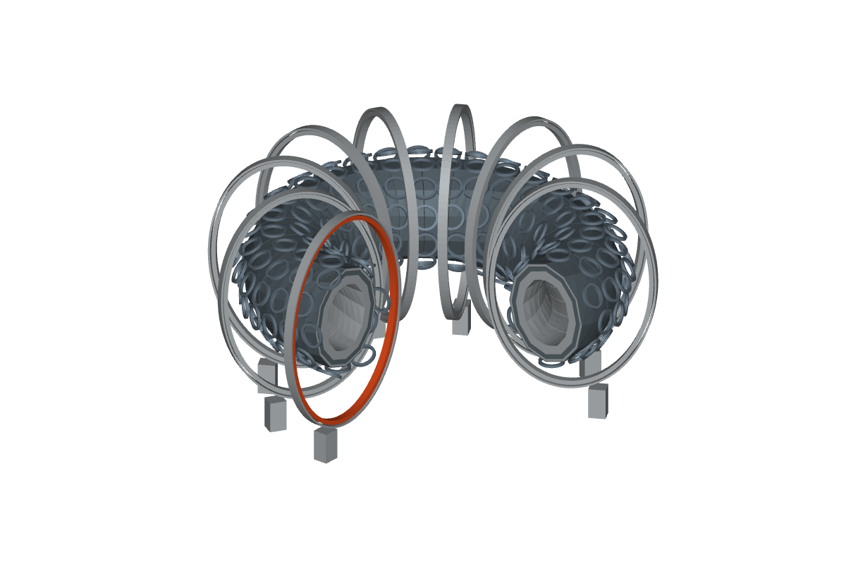 NOT A SIMULATIONMETRES · RECONSTRUCTED LAYOUT
All dimensions, components and sources are available below. Load 3D to orbit and inspect parts.
Continue in your CAD tools
Editable reconstructed solids, per-part IDs, source references and assumptions. Assembly placement and clearance remain unvalidated.
PUBLISHED DIMENSIONS
From the first wall to the outer shield
The nominal 14-layer build from the blanket paper, Table 2. Thicknesses total 997.95 mm; the plasma gap, coil casing and service clearance are additional. Source ↗
| Layer | Material / region | Thickness (mm) | Outer offset (mm) |
|---|---|---|---|
| Plasma-facing plate | V-4Cr-4Ti | 2.75 | 2.75 |
| Front helium channel | Helium | 6.35 | 9.1 |
| Middle plate | V-4Cr-4Ti | 2.5 | 11.6 |
| Rear helium channel | Helium | 6.35 | 17.95 |
| Back plate | V-4Cr-4Ti | 2.5 | 20.45 |
| Breeding zone | Pb-17Li / EUROFER97 / He / SiC | 500 | 520.45 |
| Fast-neutron shield | Tungsten carbide | 230 | 750.45 |
| Absorbing shield | Boron carbide | 70 | 820.45 |
| Inner vessel shell | 316L stainless steel | 20 | 840.45 |
| Vessel vacuum gap | Vacuum | 10 | 850.45 |
| Middle vessel shell | 316L stainless steel | 30 | 880.45 |
| Vessel cooling layer | Borated water | 17.5 | 897.95 |
| Outer vessel shell | 316L stainless steel | 50 | 947.95 |
| Outer shield | Borated polyethylene | 50 | 997.95 |
COMPONENT DETAIL
Inside one shaping coil
The demanding coil in the engineering study has 18 double pancakes, each with 688 turns and two HTS tapes per turn. Its winding bore is 1.19 m and its outside diameter is 1.50 m. The detailed view separates winding layers, copper cooling plates, remountable joints, clamping plates and 120 bolts. §2.2 and Table 1 ↗
Keep the design models distinct
The physics coil centerline is a 1.337 m circle. The finite-build engineering coil has 1.19 m and 1.50 m inner and outer diameters. These are different representations. The 18-pancake edge case does not establish the stack count for all 324 coils.
The 3D close-up uses assumed plate thicknesses, ring widths, bolt circles, clearances and clamp geometry. Threads and exact supplier tape layers are not modeled.
EVIDENCE & NEXT STEPS
What the model can support
Inspect the architecture, trace published dimensions and prepare a more detailed CAD study. Each subsystem below links to its research basis and the information needed for analysis.
Plasma envelope
Two field periods; the displayed boundary is an authored approximation. The equilibrium file and Fourier coefficients are not included in the publications inspected.
Obtain the published equilibrium and coordinate convention before magnetic or transport analysis.
Research basis ↗12 encircling coils
Planar winding packs and supporting cases. The repeated oval profile, varying tilts and case dimensions are approximations; the three unique published coil contours are unavailable.
Obtain coil centerlines, winding-pack cross-sections and supports; assess magnetic loads and quench protection.
Research basis ↗324 shaping coils
Circular finite-build envelopes use the published edge-case 1.19 m bore and 1.50 m outside diameter. Array placement and stack heights are illustrative.
Obtain all 324 transforms, currents and double-pancake counts before field reconstruction.
Research basis ↗First wall & channels
Five separately selectable plate and helium layers reproduce Table 2 thicknesses. Coolant layers represent occupied regions, not machined channels.
Resolve channel routing, joining, surface heat loads and radiation damage.
Research basis ↗Breeding blanket
50 cm nominal mixed-material breeding zone, split into 24 display sectors. No internal flow-channel routing is inferred.
Replace the homogeneous envelope with channel-resolved geometry for coupled flow, heat and tritium analysis.
Research basis ↗Neutron shielding
23 cm tungsten carbide, 7 cm boron carbide, and 5 cm borated polyethylene layers.
Resolve penetrations, local support structures and streaming paths before using any shielding result.
Research basis ↗Plasma vessel
Five steel, vacuum and water layers follow the published radial build. Sector joins and seals are approximate.
Obtain vessel joint, coolant manifold and seal geometry; check pressure, thermal and structural loads.
Research basis ↗Divertor & exhaust
Upper and lower target envelopes show the double-null architecture. Contours and locations are illustrative; exhaust domes and pumping ducts are not modeled.
Obtain target surfaces, pumping conductance, cooling channels and plasma boundary conditions.
Research basis ↗Coil & gravity supports
Gravity support feet provide spatial context. Member sizes, load paths and attachment positions are authored; detailed coil bracing is not reproduced.
Obtain load paths, connections and boundary conditions before structural assessment.
Research basis ↗Cryostat & access panels
12 radial wedges; 15.2 m radius; 19.2 m internal height; 4.9 × 12.2 m side covers. Dome profile and frame details are approximate.
Resolve seals, stiffeners, feedthroughs and remote handling clearances.
Research basis ↗| Quantity | Reported value | Scope |
|---|---|---|
| Plasma on-axis field ↗ | 6 T | Published equilibrium design point |
| Optimized coil-set peak field ↗ | 19.4 T | Finite-build optimization model |
| Encircling-coil peak field ↗ | 20.5 T | Most demanding coil engineering study |
| Shaping-coil peak field ↗ | 21.4 T | Edge-case coil, self-field plus background |
| Nominal radial build ↗ | 0.99795 m | Sum of Table 2; no plasma gap or coil casing |
| Idealized breeding ratio ↗ | 1.30 | Published homogeneous model at 65% lithium-6 enrichment; not a result from this reconstruction |
| Fusion / net electricity ↗ | 958 MW / approximately 390 MW | Published plant design study, not an operating measurement |
Model assumptions and missing source data
- The original CAD, equilibrium coefficients, coil transforms, per-coil currents and full assembly tolerances were not obtained. The coil paper states that data are available on request.
- No magnetic field, heat-flux, neutron, tritium, structural or plant-performance calculation is run by this viewer. No physics validation is attached to these meshes or STEP files.
- The analytic two-period surface and uniform display segmentation preserve selected dimensions but do not reproduce the optimized Helios equilibrium or its exact plasma volume.
- Radial thicknesses are nominal poloidal offsets in this reconstruction, not exact normal offsets to the true three-dimensional plasma surface. The plasma-to-wall gap is an assumption.
- Coil coordinates, cooling routes, internal blanket channels, support members, joints, bolt placement and dome curvature require further source data. Assembly-wide collision clearance and maintenance motion are not certified.
- The detailed coil uses the demanding 18-double-pancake design. Array envelopes do not imply 18 double pancakes at every position.
- The 20 T overview limit, 19.4 T coil-optimization result, 20.5 T encircling-coil study and 21.4 T shaping-coil edge case refer to different models. They are retained separately, not treated as one validated limit.
Design publications
The collection was supplied on September 9, 2026. Individual issue dates run August–November 2026; a same-day publication date is not asserted. Online publication dates were not provided by the Crossref metadata used here.
- MHD stability analysis of the Helios stellarator fusion power plant ↗2026-10 · Abstract or metadata reviewed; see linked paper
- The Helios cryostat, maintenance schemes, and cryogenic production system ↗2026-11 · Full text reviewed for geometry
- Electrical and power supply systems of Helios fusion power plant ↗2026-10 · Abstract or metadata reviewed; see linked paper
- Planar coil design for the Helios stellarator fusion power plant ↗2026-09 · Full text reviewed for geometry
- Equilibrium optimization of the Helios planar coil stellarator power plant ↗2026-09 · Abstract or metadata reviewed; see linked paper
- Alpha confinement in the quasi-axisymmetric Helios fusion power plant ↗2026-08 · Abstract or metadata reviewed; see linked paper
- The Helios stellarator fusion power plant: Scoping studies, heating, and fueling ↗2026-11 · Abstract or metadata reviewed; see linked paper
- Superconducting planar coils for magnetic field shaping in the Helios Stellarator ↗2026-09 · Full text reviewed for geometry
- Control, diagnostic, and instrumentation systems of the Helios fusion power plant ↗2026-08 · Abstract or metadata reviewed; see linked paper
- Core profile prediction and transport analysis of the Helios stellarator fusion power plant ↗2026-09 · Abstract or metadata reviewed; see linked paper
- Design of the superconducting encircling coils for Helios, the planar coil stellarator ↗2026-09 · Abstract or metadata reviewed; see linked paper
- Overview of the helios design: A practical planar coil stellarator fusion power plant ↗2026-11 · Abstract or metadata reviewed; see linked paper
- Facility power balance, thermodynamic cycle, and fuel cycle analysis for the Helios fusion power plant ↗2026-09 · Abstract or metadata reviewed; see linked paper
- Design and conceptual modeling of a tokamak-like X-point divertor for the Helios quasi-axisymmetric stellarator ↗2026-09 · Abstract or metadata reviewed; see linked paper
- Preliminary engineering design of the first wall and X-point divertor of the Helios planar coil stellarator ↗2026-10 · Abstract or metadata reviewed; see linked paper
- Preliminary nuclear and thermal analysis of a dual-coolant lead-lithium blanket concept for the Helios fusion power plant ↗2026-10 · Full text reviewed for geometry
- Overview of the Helios Design — December 2025 preprint, version 1 ↗2025-12-08 · Full text reviewed; retained separately from 2026 journal versions